


Request a Quote
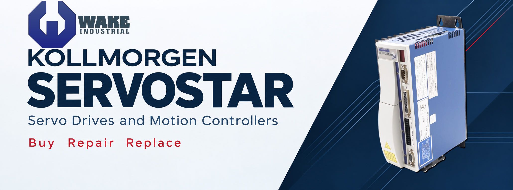
Kollmorgen SERVOSTAR Drives
To receive a comprehensive, industry competitive quote now, call Wake Industrial at 919-443-0207. You can also contact Wake Industrial by filling out the quote form embedded on the page or by sending an email to sales@wakeindustrial.com. You will receive a response within 15 minutes during business hours. SERVOSTAR systems control motor current, speed, and position, with products ranging from compact DC-powered drives to mains-fed servo amplifiers and multi-axis motion controllers. Selecting the right unit requires more than matching an amperage rating: supply voltage, motor feedback, command interface, and stored configuration all affect suitability. A replacement must also fit the machine’s control architecture, whether it uses an MC controller, an SP power amplifier, or an S400 master-and-axis arrangement. Wake Industrial can review your unit details and quote repair or replacement options for the installed system.
CD Servostar CD Drives
CD Servostar CD Drives combine digital current, velocity, and position control with sinusoidal motor commutation. Command options include analog ±10 V, serial commands, encoder following, pulse and direction, and SERCOS on appropriately equipped units. Resolver, incremental-encoder, and sine-encoder versions allow the drive hardware to match different motor feedback systems. Auxiliary encoder feedback supports dual-loop control or master-and-slave operation, while electronic gearing and stored indexing profiles provide additional ways to coordinate motion.
Logic-power configuration and control interface are important replacement details. External 24 VDC logic versions allow the control electronics to be powered separately from the mains supply, and MOTIONLINK provides parameter setup, tuning, monitoring, and backup functions. CD-Lite variants emphasize digital current and velocity control, with RS-232 communication and a different connector set from the full CD platform. Their feedback options also differ; resolver-equipped CD-Lite units require external 24 VDC logic power. Match these features before treating CD and CD-Lite units as alternatives.
Part number | Nominal AC input | Continuous output current | Peak output current for 500 ms |
115/230 VAC; 1 or 3 phase | 3 A rms | 9 A rms | |
115/230 VAC; 1 or 3 phase | 6 A rms | 18 A rms | |
230 VAC; 3 phase | 10 A rms | 20 A rms |
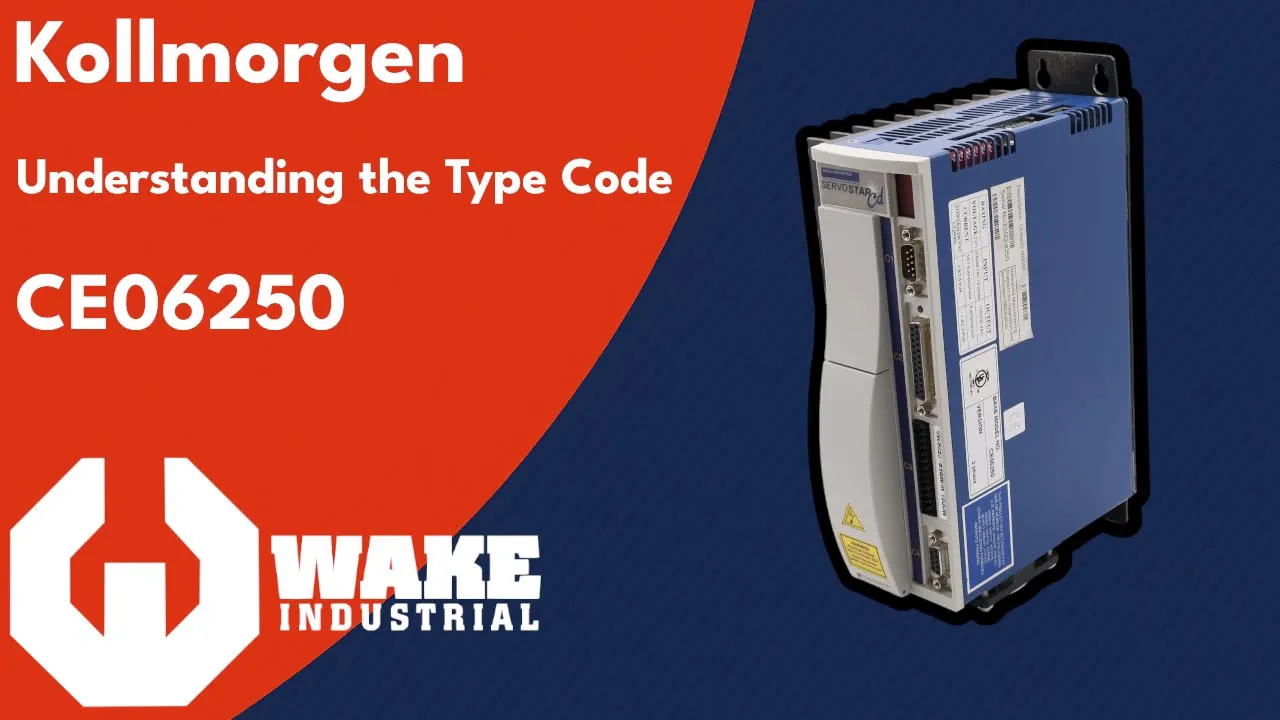
MC Servostar Servo Drives
SERVOSTAR MC products are multi-axis motion controllers that exchange commands and feedback with separate servo drives over a SERCOS fiber-optic ring. MC-BASIC supports point-to-point positioning, linear and circular interpolation, electronic gearing, camming, and event-driven tasks. This allows one controller to coordinate several axes and manage machine sequences. The controller has its own processor and operating environment; PC plug-in versions do not rely on the host processor to execute their motion-control tasks.
Hardware choices include PC cards, standalone units, and extended standalone packages with option-card provisions. Axis capacity, RAM, flash storage, and processor configuration must suit the existing application. Ethernet and serial connections support interaction with the controller, while PC/104 expansion accommodates additional I/O. A replacement also needs the machine project, startup configuration, axis definitions, and appropriate communication settings. Preserve the existing programs and parameter files before removing a functioning controller, because matching the hardware number alone does not restore the machine sequence.
Part number | Package | Axes | RAM | Flash storage |
Extended standalone | 5 | 32 MB | 24 MB | |
Standalone | 8 | 32 MB | 24 MB | |
Extended standalone | 16 | 8 MB | 8 MB |
PD Servostar Servo Drives
PD Servostar Servo Drives, also called Pico drives, provide current, velocity, and position control from an external low-voltage DC bus. The product design includes nominal 24 VDC and 80 VDC bus versions, with separate 24 VDC logic power. This supply arrangement is a key distinction when replacing a drive in a compact machine. The bus-voltage code must match the installed power supply; a mains-fed SERVOSTAR drive cannot be selected solely because it has a similar current rating.
Control capabilities include analog commands, encoder following, pulse and direction, and SERCOS on the corresponding interface version. Available feedback configurations include incremental encoders, sine encoders, and resolvers. MOTIONLINK supports motor configuration, tuning, parameter backup, and fault monitoring. Position functions include homing, incremental and absolute moves, electronic gearing, and dual-loop operation using separate motor and load feedback. Selection therefore requires checking the DC bus, feedback hardware, command interface, and required motion functions together.
Part number | Nominal DC bus | Continuous output current | Feedback |
24 VDC | 5 A rms | Incremental encoder | |
24 VDC | 10 A rms | Incremental encoder | |
80 VDC | 5 A rms | Sine encoder |
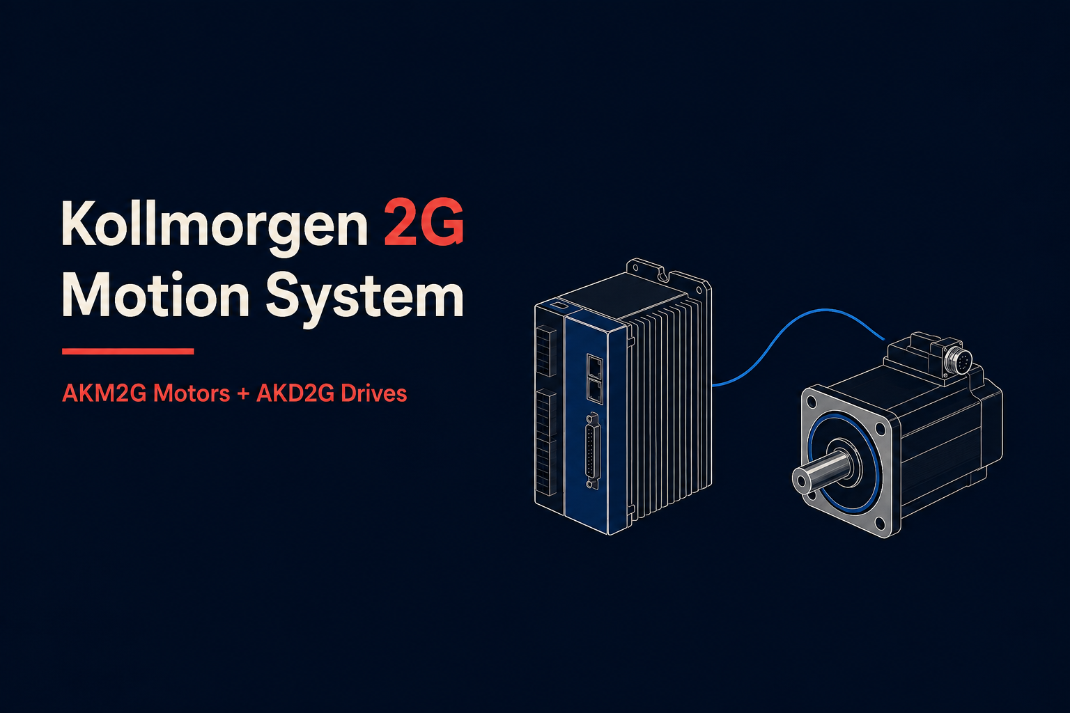
SC Servostar Servo Drives
SC Servostar Servo Drives combine single-axis control with a servo power stage for brushless synchronous motors. The model code identifies the feedback arrangement, with R for resolver, E for encoder, and B for sine encoder. The controller supports closed-loop torque, speed, and position operation and uses a separate 24 VDC logic supply. PC communication is available through serial and Ethernet connections, allowing access to configuration and operating information independently of the motor power connections.
Replacement checks should include both hardware enable and motion enable, the configured operating mode, and any motor-compensation information in the full type code. These details affect whether a correctly powered unit can produce motion. The 3 A and 6 A versions support 115 VAC single-phase or 230 VAC single- or three-phase input, while the 10 A version requires 230 VAC three-phase input. Match the feedback type and supply arrangement before transferring motor settings or attempting to run the replacement.
Part number | AC input options | Current rating | Feedback |
115 VAC 1 phase; 230 VAC 1 or 3 phase | 3 A | Encoder | |
115 VAC 1 phase; 230 VAC 1 or 3 phase | 6 A | Resolver | |
230 VAC 3 phase | 10 A | Sine encoder |
SP Servostar Servo Drives
SP Servostar Servo Drives include power amplifiers designed to work with an external control system and a separate power-supply module. The original SP platform can operate with externally closed current loops and PWM commands, internally closed current loops using analog phase-current commands, or six-step commutation with Hall signals. The compensation header determines the applicable control mode and current-loop compensation. This makes the controller interface and compensation arrangement central to replacement selection, alongside the output-current and DC-bus ratings.
The SP model code distinguishes the standard interface from the Delta Tau interface. Its separate supply module provides the DC bus and control voltages, with regeneration handling determined by the supply and resistor configuration. SP3 power blocks use a different CP3 model format and mains-input arrangement, with options for internally generated or external logic power. Identify whether the existing unit is an original SP amplifier or an SP3 power block before comparing candidates, and retain the complete motor-compensation and option suffixes.
Part number | DC input range | Continuous output current | Interface |
125–360 VDC | 3 A rms | Standard | |
125–360 VDC | 6 A rms | Delta Tau | |
295–360 VDC | 20 A rms | Standard |
Start with the complete nameplate number and the machine configuration. Use the following checks to narrow a replacement before comparing price or lead time.
| Selection point | What to confirm |
| Product role | Identify a servo drive, MC motion controller, SP power amplifier, or S400 master/axis module. |
| Power architecture | Match AC voltage and phase count, or the external DC-bus voltage. Confirm the separate logic and control supplies. |
| Current and duty | Compare continuous output current at the applicable supply and switching conditions. Keep peak current and its permitted duration separate. |
| Motor feedback | Match resolver, incremental encoder, sine encoder, and any required feedback protocol or motor compensation. |
| Commands and networks | Confirm analog, pulse-direction, PWM, SERCOS, CANopen, or the exact fieldbus option fitted to the machine. |
| Stored configuration | Retain motor parameters, tuning, I/O assignments, firmware details, and MC application and startup files. |
| Braking and cooling | Check the supply or brake-resistor arrangement, required ventilation, and cabinet operating conditions. |
Record the exact indication and the operating conditions before clearing a fault. Diagnostics differ between families. Electrical checks should be performed by qualified personnel, with power isolated and the DC bus verified discharged before touching connections. Contact Wake Industrial today by calling 1-919-443-0207 or by sending an email to sales@wakeindustrial.com to receive a comprehensive repair quote.
Symptom | Applicable family | First checks |
Drive fault or current foldback | CD and PD | Read the fault history and operating status in MOTIONLINK. Review motor setup, load duty, and the recorded fault before resetting. |
Powered but no motion | SC | Check hardware enable, motion enable, operating mode, and motor configuration. Logic power alone does not establish motion readiness. |
Axes unavailable over SERCOS | MC | Check ring continuity, drive addressing, startup configuration, and communication phase. Normal SERCOS operation is phase 4. |
Under-voltage indication | Original SP | Check the separate supply, incoming-power status, fuses, and DC-bus connections. Record the supply and amplifier LED states together. |
Over-voltage indication | Original SP | Check the supply and regeneration arrangement. An inadequate shunt resistor or a supply fault can raise the DC bus beyond its limit. |
Motor does not rotate | S300 and S400 | Check enable status, command wiring, brake release, mechanical blockage, motor phase assignment, and feedback setup. |
Motor oscillates or runs roughly | S300 and S400 | Review feedback-cable shielding, analog ground, and tuning parameters against the motor and machine configuration. |









