


Request a Quote
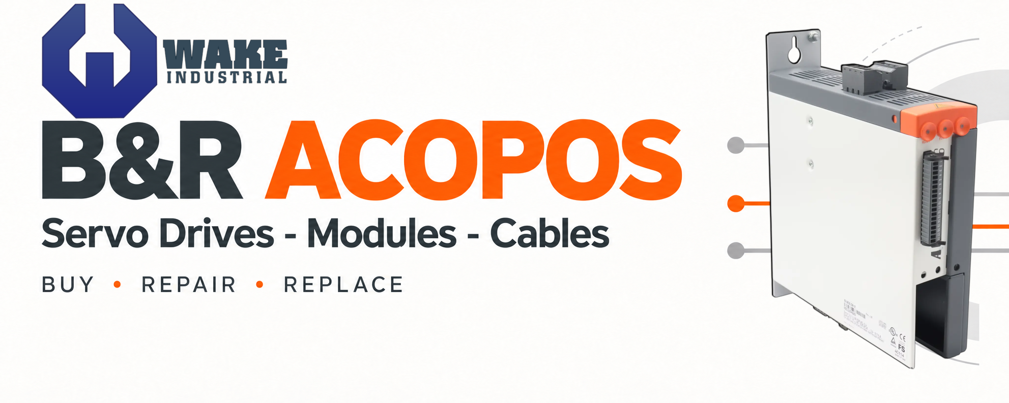
B&R ACOPOS Servo Drives, Modules, and Cables
Get a quote FAST for all B & R Automation ACOPOS products from Wake Industrial; receive a response in as fast as 15 minutes. Request a quote now or call 1-919-443-0207. Request a quote for ACOPOS servo drives, ACOPOS P3, ACOPOSmulti, ACOPOSmicro, ACOPOSremote, and ACOPOSmotor components, including the plug-in modules and cables required by your installation.
Replacing an ACOPOS component starts with identifying its function within the machine. A cabinet-mounted servo drive, shared-bus inverter, regenerative power supply, and motor with integrated drive electronics perform different jobs. The complete ordering code, feedback interface, cooling arrangement, safety configuration, and connected accessories help determine the correct replacement.
ACOPOS Servo Drives
ACOPOS drives combine servo control with configurable communication and feedback connections. Sampling and communication cycles of 400 µs, together with control-loop cycles as short as 50 µs, support applications requiring rapid responses to machine events. Standard axis I/O includes two trigger inputs for measurement and registration tasks.
Integrated filtering supports electromagnetic compatibility, while thermal models use measured currents and temperatures to manage operation. Compatible motor parameter chips provide mechanical and electrical motor data, reducing manual parameter entry. Partially coated circuit-board versions are also available for improved resistance to environmental influences. Plug-in modules adapt the drive to the required network, encoder, sensor, or controller connection.
Part Number | Rated Power | Continuous Output Current | Peak Output Current | Braking Resistor Power, Continuous / Peak | Weight |
0.7 kW | 1.6 Aeff | 5 Aeff | 130 W / 2 kW | 2.5 kg | |
2 kW | 4.4 Aeff at 400 V; 3.3 Aeff at 480 V | 24 Aeff | 200 W / 7 kW | 4.1 kg | |
4 kW | 8.8 Aeff at 400 V; 6.6 Aeff at 480 V | 24 Aeff | 200 W / 7 kW | 4.4 kg |
ACOPOS P3: 8EI Servo Drives
ACOPOS P3 combines one, two, or three controlled axes in a single drive housing. Each axis has an integrated digital multi-encoder interface, and the product range includes different supply-voltage classes, current ratings, and safety configurations. Coated circuit boards provide additional resistance to dust and moisture, while separate axis indicators help identify the operating state of each motor channel.
The ordering code also specifies supplied plug-in modules and configurable accessories. Two drives with the same current rating can differ in their internal braking resistor, front cover, connector set, or feedback options. For example, 8EI017HWS10.0200-1 and 8EI017HWS10.0600-1 share the same basic voltage and current class, but the latter configuration includes an internal braking resistor. These details matter when matching an existing installation.
Product Number | Controlled Axes | Supply Voltage | Continuous Current per Axis | Internal Braking Resistor |
1 | 3 × 200–480 VAC | 17 Aeff | No | |
1 | 3 × 200–480 VAC | 17 Aeff | Yes | |
2 | 3 × 200–480 VAC | 4.5 Aeff | Yes |
ACOPOSmulti: Inverter and Power Supply Modules
ACOPOSmulti separates the power supply, auxiliary supply, and motor inverter functions into modules connected through a common backplane. The mounting system distributes the DC bus and auxiliary supply between components, supporting machines with multiple coordinated axes. Single-axis and dual-axis inverter configurations allow the drive arrangement to follow the number and loading of the machine’s motors.
Active 8BVP power supplies provide power-factor correction and return regenerative energy to the mains. The 8BVI inverter modules control the connected motors and accept plug-in feedback interfaces. Cooling is another major selection factor: wall-mounted versions release heat into the cabinet, while cold-plate and feed-through arrangements use different heat-removal paths. Matching electrical ratings alone does not establish mechanical or thermal compatibility.
Product Number | Component Function | Nominal DC Bus | Rated Output | Mounting |
Single-axis inverter | 750 VDC | 3.8 Aeff; 2.8 kW motor output | Cold plate or feed-through | |
Single-axis inverter | 750 VDC | 44 Aeff; 32 kW motor output | Wall mounting | |
Active power supply | 750 VDC | 30 kW continuous supply and regeneration | Cold plate or feed-through |
ACOPOSmicro: 80VD Inverter Modules
ACOPOSmicro 80VD modules control one or two servo motors from a DC supply. The documented configurations use a 24–64 VDC supply range with ±25% tolerance and provide 8 ARMS nominal motor current under the specified operating conditions. POWERLINK communication, Automation Studio integration, and PLCopen operation connect these compact axes to the machine’s motion-control system.
Feedback configuration is a key distinction between models. Available variants include EnDat 2.2, resolver, SSI, SinCos, incremental, and other interfaces. The ordering code also identifies the number of motor connections, cooling concept, and I/O arrangement. Switching frequency must be considered alongside current demand because higher-frequency operation can require current reduction.
Product Number | Motor Connections | Feedback | Power Supply | Nominal Motor Current |
2 | Two EnDat 2.2 interfaces | 24–64 VDC ±25% | 8 ARMS per motor | |
2 | Two resolver interfaces | 24–64 VDC ±25% | 8 ARMS per motor | |
1 | One EnDat 2.2 interface | 24–64 VDC ±25% | 8 ARMS |

ACOPOSremote: 8CVI Inverter Modules
ACOPOSremote moves the inverter from the control cabinet to the machine. Hybrid connections distribute power and communication between decentralized components, while separate motor and feedback connections serve the controlled axis. This arrangement supports modular machinery without requiring every motor cable to return to a central drive cabinet.
The 8CVI045 variants below share a current class but use different feedback interfaces. Their cold-plate mounting arrangement, motor-cable limits, and connector sealing requirements are part of the installation specification. IP65 protection requires the appropriate connections and covers on unused ports; the rating does not apply to an incompletely sealed module.
Product Number | Feedback Interface | Nominal DC Bus | Continuous Motor Current | Continuous Motor Power |
SinCos | 750 VDC | 4.5 Aeff | 1.5 kW | |
SinCos EnDat 2.1 / SSI / BiSS | 750 VDC | 4.5 Aeff | 1.5 kW |
ACOPOSmotor: 8DI Integrated Motor and Drive Units
ACOPOSmotor combines the servo motor, drive electronics, and position sensor in one assembly. Hybrid connections carry the required power and network signals, allowing the units to form part of a decentralized motion system. The motor flange also participates in heat removal, making the mounting arrangement relevant to the unit’s operating capability.
Replacement selection must account for both electrical and mechanical options. The 8DI ordering code identifies motor size and length, safety technology, encoder, nominal speed, electronics options, shaft design, oil seal, and holding brake. Some configurations also provide an additional POWERLINK connection, two 24 VDC outputs, and two trigger inputs. A matching motor size alone does not confirm that these features are present.
Product Number | Nominal Speed | Encoder | Shaft | Holding Brake |
2,200 rpm | EnDat 2.2 single-turn | Smooth | No | |
2,200 rpm | EnDat 2.2 multiturn | Keyed | Yes | |
4,500 rpm | EnDat 2.2 multiturn | Keyed | Yes |
Identify the Complete Assembly
Record the full drive or motor number, hardware revision, installed plug-in modules, and cable numbers before requesting a replacement. For ACOPOSmulti installations, identify whether the problem involves an inverter, active supply, auxiliary supply, expansion module, or cooling component. These components share the system but perform different functions.
Match Supply and Current Requirements
Distinguish mains-powered drives from modules connected to a DC bus. Within ACOPOS P3, the supply-voltage code separates the 200–480 VAC class from lower-voltage configurations. ACOPOSmicro 80VD modules use a DC power supply. For multi-axis units, verify the current available per motor connection and any limits affecting simultaneous operation.
Confirm Feedback and Safety Configuration
Match the motor’s feedback system to the drive interface and installed option module. Resolver, EnDat, SinCos, SSI, and other feedback arrangements require the appropriate hardware and configuration. Check whether the machine uses hardwired STO or a SafeMOTION configuration, and preserve the required safety functionality when selecting replacement equipment.
Check Cooling, Cabling, and Included Accessories
Wall mounting, cold-plate mounting, and feed-through mounting require different thermal arrangements. Confirm the intended cooling method, cabinet conditions, switching frequency, and applicable derating. Also check whether the replacement includes the braking resistor, connector set, front cover, terminal blocks, and feedback accessories required by the machine.
Record the complete diagnostic message, affected axis, LED state, and circumstances of the fault before resetting the system. Qualified personnel should isolate equipment and follow the applicable discharge procedure before inspecting electrical connections.
Family / Indication | Meaning or Possible Condition | Initial Checks |
ACOPOS P3: PLK indicator solid red | POWERLINK node number is 0 | Check the node-number setting against the machine configuration. |
ACOPOS P3: axis indicator blinking green | Axis is not ready; possible enable, DC-bus, feedback, temperature, or network issue | Read the detailed diagnostic and check the corresponding enable signals, supply status, feedback connection, and thermal condition. |
ACOPOS P3: axis indicator solid red | Permanent module error | Record the diagnostic before resetting; investigate the reported fault and request repair evaluation if it persists. |
Original ACOPOS with 8AC114.60-2: R/E indicator blinking red/green | POWERLINK client has entered an error state and left cyclic operation | Check the controller’s network diagnostic, cable connections, node settings, and affected network segment. |
Documented ACOPOSremote 8CVI variants: error 6060 | Electrical output-frequency limit exceeded | Check commanded speed and configured motor pole-pair count. Do not treat this as a generic overload indication. |
ACOPOSmicro 80VD: supply-related shutdown | Power-stage supply outside the permitted range | Check the recorded DC-supply value and whether the event occurs during acceleration or braking. The documented cutoff thresholds are below 18 VDC and above 95 VDC. |