


Request a Quote
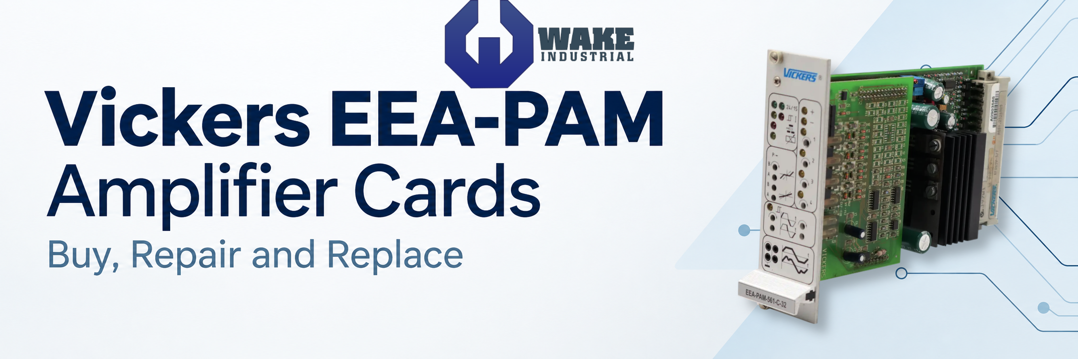
Vickers EEA-PAM Amplifier Cards: Specs, Sales, and Services
Get a quote FAST for all Vickers EEA-PAM cards from Wake Industrial; receive a response in as fast as 15 minutes. Request a quote now or call 1-919-443-0207. Vickers EEA-PAM amplifiers connect electrical command signals to hydraulic valve solenoids. Depending on the model, the card conditions the command, regulates solenoid current, processes valve spool feedback, or provides an integrated PID controller for an external pressure, velocity, or position loop. Selecting the correct replacement requires matching the complete amplifier code to the valve and control circuit. Each card features a user-friendly front panel with status LED indicators and adjustment potentiometers, making it easy to tune performance on-site and monitor a systems status. In short, Vickers EEA-PAM cards offer an all-in-one solution to optimize hydraulic actuator performance while reducing downtime and simplifying troubleshooting.
Match the Complete Amplifier Number
Record every number and suffix on the installed card. EEA-PAM-535-A-32 identifies a particular amplifier and valve interface; matching only EEA-PAM or the letter A is insufficient. Keep the existing card number, valve number, and machine wiring information together when requesting a quote.
Confirm Valve and Output Requirements
Check the valve family, coil type, solenoid arrangement, and feedback connections. The A-32 examples above range from 1.6 A to 2.7 A maximum solenoid current, while other A designs use substantially lower servo valve currents. A higher current rating does not establish compatibility with the installed valve. A EEA-PAM-525-C-32 is not the same as a EEA-PAM-118-B-30, for example.
Separate Valve Feedback from Machine Feedback
Valve LVDT feedback measures spool position. An external sensor used by a PID controller measures the controlled machine variable, such as pressure or position. Identify both interfaces where present, including signal range and polarity, before selecting a replacement.
Check Supply and Connector Requirements
Confirm the supply range for the complete model, rather than relying on the nominal 24 V designation. The A-32 and 56*-A-14 designs have different permitted supply ranges. Also check the mating connector and occupied pin rows; D-32 cards require the F48 connection for their additional control functions.
Preserve the Existing Configuration
Record switch positions and application settings before removing a card. Relevant settings can include gain, deadband or zero adjustment, ramps, sensor scaling, and PID parameters. A replacement with the correct part number still needs its configuration checked against the machine before returning to operation.
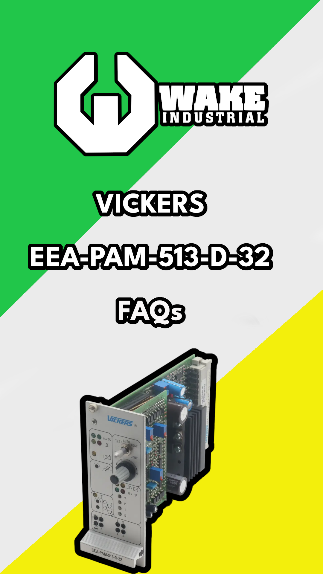
A-32 Proportional Valve Control
EEA-PAM A-32 amplifiers use pulse-width-modulated output stages to drive proportional valve solenoids. Their signal-conditioning functions determine how the valve responds to the machine command: gain adjusts the command-to-output relationship, zero adjustment or deadband compensation establishes the response around neutral, and ramps limit how quickly the output changes. The available adjustments depend on the amplifier model and its associated valve.
A-32 cards have five voltage inputs, including one inverting input, plus a current input. They use a nominal 24 V DC supply, with an operating supply range of 20 to 40 V DC and a full-specification ambient range of 0 to 50°C. Separate acceleration and deceleration ramp adjustments cover 50 milliseconds to 5 seconds. Front-panel LEDs indicate supply and output status, while monitor points expose the conditioned command and either solenoid current or valve spool position.
Feedback capability and output current vary within the A-32 group. EEA-PAM-513-A-32 and EEA-PAM-525-A-32 monitor solenoid current, while EEA-PAM-535-A-32 uses valve spool LVDT feedback. The LVDT measures spool position; it does not make every A-series card an external pressure or position PID controller. The correct valve interface remains essential when selecting a replacement.
Model | Associated valve types | Maximum solenoid current | Output monitoring |
KCG-3, KCG-6/8, and KX(C)G-6/8, 1 series | 1.6 A | Solenoid current; MP2 scale of 1 V/A | |
KTG4V-5 and KDG4V-5 with H-type coils, 3 series | 1.6 A | Solenoid current; MP2 scale of 1 V/A | |
KFTG4V-5 and KFDG4V-5, 2 series | 2.7 A | Spool LVDT position; MP2 full-stroke signal of ±10 V |
Vickers EEA-PAM D-Series Amplifiers
EEA-PAM D-32 cards combine a proportional valve power amplifier with an integrated PID module. The PID controller compares an external command with a feedback signal and adjusts the valve command to reduce the difference. Configurable operating modes support closed-loop pressure, velocity, and position control, along with pressure/flow control using internal or external switching from flow control to pressure control.
The PID module provides proportional, integral, derivative, and feed-forward adjustments. Its sensor interface accepts 0 to 10 V, ±10 V, 0 to 20 mA, or 4 to 20 mA feedback, with configuration matched to the sensor. Command and feedback voltage ranges must correspond. Sensor-failure monitoring applies to the 4 to 20 mA feedback configuration; it should not be assumed to detect faults on every supported sensor input.
Front-panel monitor points separate the conditioned valve command, command signal, feedback signal, PID output, and integrator output. The mode switch selects AUTO, TEST VALVE, or TEST LOOP. AUTO uses the external command; the two test modes use the front-panel test potentiometer to evaluate the valve or closed-loop response. This distinction helps identify whether a problem lies in the valve response or the external control loop.
Model | Associated valve types | Control functions | External sensor feedback |
KHDG5V-5/7/8 | Integrated PID, feed-forward, command ramps, and configurable pressure/flow control | 0 to 10 V, ±10 V, 0 to 20 mA, or 4 to 20 mA | |
KF*G4V-5 | Integrated PID, feed-forward, command ramps, and configurable pressure/flow control | 0 to 10 V, ±10 V, 0 to 20 mA, or 4 to 20 mA |

Common Vickers EEA-PAM Troubleshooting Steps
Symptom | Applicable design | Checks before requesting repair |
Card has no output and supply indications are abnormal | A-32 | Verify the supply at the card. The operating range is 20 to 40 V DC; amplifier shutdown occurs below 18 V DC. |
Supply indications are present but the output is disabled | A-32 and D-32 | Check the drive-enable input at z24. On D-32 cards, also check the separate PID-controller and integrator enable states where required by the application. |
Solenoid overload indication is active | A-32 and D-32 | Inspect the solenoid circuit and wiring for the overload cause. After correction, the latched alarm output is reset by disabling and re-enabling z24. |
LVDT failure indication is active | Models equipped for LVDT feedback | Check the applicable valve feedback connections and LVDT supply. Keep pilot-stage and main-stage connections correctly identified. |
Ramping is absent or response timing is incorrect | A-32 | Check ramp enable at b24 and the separate acceleration and deceleration settings. Compare the conditioned command at MP1 with the output response. |
Sensor-failure indication is active | D-32 with 4 to 20 mA feedback | Check the sensor current circuit and DIL-switch configuration. Do not apply this indication to voltage-feedback fault detection. |
External commands appear to be ignored | D-32 | Check that the mode switch is in AUTO. TEST VALVE and TEST LOOP disconnect the external command and use the front-panel test potentiometer. |