EEA-PAM-520-A-14

No Tariffs On US Orders
  • Straightforward Pricing: No Rush Fees, No Credit Card Fees
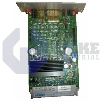
    In-Stock, Ships 3-5 Days

Preparing your secure checkout page...

The EEA-PAM-520-A-14 power amplifier card supports voltage inputs from 0 to 10 V and current inputs from 0 to 20 mA. It includes front panel monitoring points and LED indicators for status checking.

Quote Request Form:

Warranty
Wake Industrial Warranty
To contact sales for pricing and lead time:

Payment Methods

Visa
Mastercard
AmEx
Wire Transfer

Shipping Methods

DHL
UPS
FedEx
Freight

Our Credentials

Cary Chamber
DUNS Registered
SAM Registered
BBB Accredited

Product Description:

The eea-pam-520-a-14 is a power amplifier card produced by Vickers. This card is part of the company's 14 design amplifier series and is engineered to work with the KD/TG4V-3 and KDG5V-5/7/8 valve series.

The EEA-PAM series amplifier card features five inputs, with four dedicated to direct current and one for inverting. The device operates on a nominal DC input voltage of 24 V and a control output supply of 15 V. The amplifier accepts input voltages ranging from 20 V to 34 V, with increased protection against voltage ripples. It has an automatic shutdown mechanism when the voltage falls below 19 V. The acceptable current threshold ranges from 0 to 20 mA. For protection against damage, the model includes an automatic reset function to guard against short circuits and reverse polarity. The front panel provides monitoring points and LED indicators, allowing users to monitor the amplifier's status thoroughly. Additionally, the front panel features controls to tweak specific settings to suit various needs. This EEA-PAM-520 power amplifier card utilizes low supply voltage protection and pulse width modulation for enhanced efficiency. The model also supports ramp-time adjustments, with factory settings ranging from a minimum of 50 ms to a maximum of 5 seconds.

The amplifier eea-pam-520-a-14 has automatic reset capabilities when the voltage exceeds 9.8 V or falls below 40 V. The command inputs for voltage range from 0 to 10 V, and the current input ranges from 0 to 20 mA. The amplifier's command signal monitor point is located on the front panel. The amplifier card is built with short-circuit protection for all outputs. It operates efficiently within a temperature range of 0 to 50 degrees Celsius and features low temperature drift of less than 1 mV/?C.

Amplifier Shut-down
<18 V DC
Drive Signal Zero Indicator Output Resistance
50 ohms
Manufacturer
Vickers
Nominal Power Supply
24 V DC
Output Monitor Point Output
10 kohms short-circuit protected
Overload Detection
Automatic reset
Product Type
Power Amplifier Card
Protection
Reverse-polarity
Ramp-active Indicator Output
10 kohms
Weight
330 g
  • EEA PAM 520 A 14
  • EEA-PAM-520-A-l4
  • EEAPAM520A14
Symptom / LED Pattern Likely Cause (What it Means) Recommended Corrective Action
All panel LEDs dark 24 V DC supply absent or reversed Verify 24 V (18-32 V) at back-plane, check fuse/polarity, then repower card.
24 V OK LED on, but +15 V logic LED off Internal logic regulator fault Measure Vlogic test-point; if 0 V replace regulator or whole card.
Yellow “Output-enable” LED dark although z24 > +10 V Enable line < 6 V, broken PLC output or wiring Trace enable wire, restore > +10 V to pin z24 and reset card. 
Red “Overload” LED lit Solenoid current > 1.5 A (shorted coil) Measure coil R; repair wiring, fit correct valve coil; card auto-resets.
Only Channel B responds (dual-out card) Channel A gain set to zero or set-min pot fully CCW Read monitor jack a18; readjust gain / set-min for Channel A.
Ramp pot turns but valve still jerks Ramp-bypass link b12-b20 closed Open link or wire it to PLC control to re-enable ramp generator.
PWM dither absent – spool sticks Factory dither jumper missing Re-install jumper per ML-9046, or enable dither via test jack.
Output drifts as card warms Temperature drift on zero/gain Allow 15 min warm-up; re-zero set-minimum; segregate signal cables from power. 
Low-supply trip < 19 V (all LEDs drop) Undersized 24 V PSU or long cable drop Upgrade PSU ≥ 40 W, use 2.5 mm² wiring to cut losses. 
Valve unresponsive after card swap Ramp time still at 20 ms factory default Turn ramp pot CW (0.02 – 2 s range) and verify with pressure gauge.
Model Typical Application / Valve Family Command Inputs Ramp Generator Diagnostics / LEDs Max Coil Current (A)
EEA-PAM-520-A-14 Dual-channel control for two proportional coils or 2-stage valve 0–10 V ×2, 0–20 mA ×1 Single adjustable (20 ms – 2 s) 24 V, 15 V, Enable, Overload 1.5 × 2
EEA-PAM-513-A-32 Mid-size directional valves (KDG4V-3*) 0–10 V ×5 / 0–20 mA Single adjustable Power, Ramp, Fault 1.5
EEA-PAM-525-A-32 High-flow KDG4V-5 valves 0–10 V ×5 / 0–20 mA Single adjustable Low-V, Overload 1.6
EEA-PAM-535-A-32 KFD/TG4V-5 pressure/flow valves 0–10 V ×5 / 0–20 mA Single adjustable Power, Overload 1.6
EEA-PAM-561-A-14 KDG5V-5/7 spool valves with LVDT ±10 V Dual independent ↑/↓ LVDT-fail, Overload 1.8
EEA-PAM-571-A-14 KFDG5V servo spools ±10 V + ±15 V ref Four-quadrant (acc/dec each dir.) LVDT, Overload, Watchdog 2.5

Indicator / Condition

What It Means

Green “24 V” LED off

No or low 24 V DC feed reaching the card (supply < 20 V or wiring fault).

Green “15 V” LED off

On-board logic rail missing – internal regulator or card failure.

Yellow “Output-enable” LED dark although z24 is ≥ 10 V

Enable line actually < 6 V at pin z24 (broken PLC output / wiring).

Red “Overload” LED lit

Solenoid current > ≈1.5 A – shorted coil or wrong valve type.

Card drops out when supply dips below 19 V

Low-supply protection triggered; PSU underrated or long cable run.

Command signal present but no valve response

Set-minimum or Gain pots fully CCW → zero output.

Ramp pot has no effect / valve jerks

Ramp-bypass link b12–b20 left closed, disabling ramp generator.

PWM dither absent

Factory dither jumper removed, causing spool stiction.

Output drifts with temperature rise

PCB zero/gain drift; requires 15 min warm-up and re-zero, improve shielding.

Ramp time wrong after card swap

Replacement still at 20 ms factory default; adjust ramp pot (0.02 – 2 s).

Frequently Asked Questions about EEA-PAM-520-A-14:

Q: What connectivity options are available on the EEA-PAM-520-A-14?

A: The EEA-PAM-520-A-14 features five inputs. Four are for direct current and one is for inverting.

Q: How does the EEA-PAM-520-A-14 handle voltage fluctuations?

A: The amplifier operates on 24 V nominal DC input voltage. It automatically shuts down below 19 V and resets when voltage exceeds 9.8 V or falls below 40 V.

Q: What protection mechanisms are built into the EEA-PAM-520-A-14?

A: The model includes short-circuit protection and reverse polarity protection. It also features an automatic reset function to prevent damage.

Q: What are the environmental operating conditions for the EEA-PAM-520-A-14?

A: The amplifier operates efficiently within 0 to 50 degrees Celsius. It also has low temperature drift of less than 1 mV/?C.

Q: How can I monitor the status of the EEA-PAM-520-A-14?

A: The front panel of the amplifier provides monitoring points and LED indicators. These allow thorough status monitoring of the amplifier.


Internal Product Review

  • ‘‘The EEA-PAM-520-A-14 power amplifier card from Eaton Vickers is designed for KD/TG4V-3 and KDG5V-5/7/8 valves. The model features five inputs, operates on 24 V DC, and supports ramp-time adjustments. The model weighs 330 g and is equipped with automatic reset and short-circuit protection.’’

Motion Industries logo
3M logo
IBM logo
Gexpro Logo
Caterpillar logo
NASA logo
Ford logo
Vallen logo