


Request a Quote
Indramat Drive and Motor Repair
Contact Wake Industrial by calling 1-919-443-0207, sending an email to sales@wakeindustrial.com, or by filling out the quote form on this page to receive a comprehensive, industry competitive quote FAST. Indramat systems use coordinated power supplies, drive controllers, feedback devices, motors, firmware modules, and communication interfaces. A fault in one component can produce startup failures, communication problems, unstable motion, excessive heating, feedback errors, or unexpected machine shutdowns. Correct identification of the complete type code is important because components from the same series can have different current ratings, cooling methods, feedback systems, interfaces, and firmware requirements.
Wake Industrial evaluates Indramat components for electrical and mechanical faults before completing a repair. Depending on the component and failure, service may involve power-stage components, control electronics, internal power supplies, cooling assemblies, connectors, feedback devices, bearings, seals, or motor braking systems. Repaired units are tested before being returned for installation. Indramat drive and motion-control systems remain installed in CNC equipment, printing machinery, packaging lines, robotics, material-handling systems, and other automated equipment. When an aging drive controller, power supply, or servo motor fails, replacing the complete control platform may be unnecessary. Wake Industrial repairs and supplies replacements for legacy Indramat components to help restore existing machinery.
DKC Drive Controllers are part of the EcoDrive family and combine power-stage and motion-control functions within a compact drive-controller format. The type code identifies the controller line and version, type-current class, voltage category, and firmware status. Different DKC lines support different control or communication connections, including standard command interfaces, SERCOS, and PROFIBUS-DP.
A failed DKC can prevent the connected motor from enabling, interrupt communication with the machine control, or produce power-stage and feedback faults. Repair evaluation should include the power section, control-voltage circuitry, DC bus connections, motor connections, temperature-monitoring circuit, communication hardware, and firmware module.
Product Number | Type Current | Voltage Category | Control Connection |
40 A | 7 | SERCOS interface | |
100 A | 7 | PROFIBUS-DP interface | |
200 A | 7 | Standard command interface |
TVD power supply modules provide the DC bus and control voltages required by compatible Indramat modular AC drive systems. The modules connect directly to a three-phase 380 to 480 VAC mains supply at 50 to 60 Hz and produce a regulated 320 VDC bus for connected drive modules. They also supply the system electronics with 24 V control power and ±15 V signal voltages. Integrated monitoring functions communicate operating conditions to the connected drives through the system ribbon cable.
The TVD series is available in 7.5 kW and 15 kW continuous DC bus power classes. The 7.5 kW versions support 15 kW for three seconds and 22.5 kW for 0.3 seconds, while the 15 kW version supports 30 kW for three seconds and 45 kW for 0.3 seconds. These overload ratings provide additional power for temporary acceleration demands from feed axes and spindle drives. Regenerative energy produced during motor deceleration is dissipated through the internal bleeder circuit, with auxiliary bleeder modules available for applications requiring greater continuous braking power or energy capacity. A TVD repair should therefore include evaluation of the mains rectifier, DC bus regulation, control-voltage supplies, bleeder circuitry, monitoring electronics, contactor control, cooling components, and drive-system communication connections.
Product Number | Continuous DC Bus Power | Short-Term DC Bus Power, 3 Seconds | Peak DC Bus Power, 0.3 Seconds |
15 kW | 30 kW | 45 kW | |
7.5 kW | 15 kW | 22.5 kW | |
7.5 kW | 15 kW | 22.5 kW |
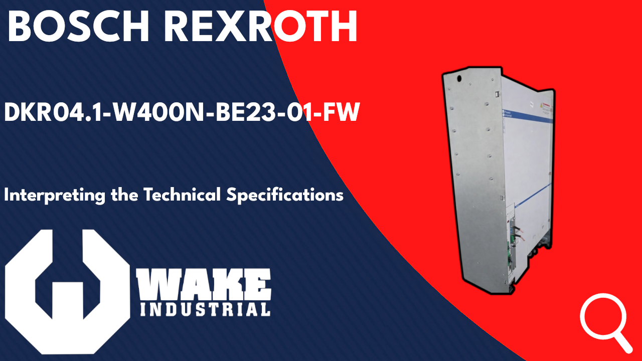
DKR Drive Controllers are designed for high-power drive applications and connect directly to a three-phase AC mains supply. The series includes 100 A and 200 A configurations with built-in blower cooling. Depending on the configuration, a DKR may include an internal brake resistor, external bleeder control, digital servo or resolver feedback support, and either analog or SERCOS command communication. They are built for direct connection to grounded 3-phase AC mains (400–480 VAC) and include an integrated mains contactor and an emergency-stop shutdown device, with regenerated braking energy returned to the mains even during an E-stop.
Repair assessment for a DKR should account for the basic unit, cooling system, command-interface card, auxiliary modules, software module, and braking circuitry. Problems in the blower, power stage, internal supplies, communication hardware, or software-module connections can prevent the controller from reaching an operational state.
Product Number | Rated Current | Cooling | Command Communication |
100 A | Built-in blower | Analog interface | |
200 A | Built-in blower | SERCOS interface | |
200 A | Built-in blower | Analog interface |
DKS servo drives combine a drive controller with an integrated power supply in a modular unit. Available type-current classes include 30 A, 50 A, and 100 A. The internal air-cooling arrangement uses a built-in blower, while the installed configuration determines the motor feedback, command interface, and functional characteristics.
Because the power supply and drive functions are integrated, a DKS failure can affect several parts of the servo system at once. Repair evaluation may include the mains input, DC bus, power stage, blower, internal control voltages, feedback connections, plug-in modules, and software module. The complete configuration code should be matched before a repaired or replacement controller is installed.
Product Number | Type Current | Cooling | Configured Control |
100 A | Internal air with built-in blower | Digital feedback and single-axis positioning | |
50 A | Internal air with built-in blower | Digital feedback and analog interface | |
30 A | Internal air with built-in blower | Digital feedback and single-axis positioning |
MKD synchronous servo motors are permanent-magnet motors designed for use with compatible digital drive controllers. Their type codes identify the motor frame and length, winding, feedback configuration, output shaft, holding brake, electrical connection direction, and housing design. MKD motors use resolver-based feedback, with certain versions providing multiturn absolute position detection.
Common MKD repair concerns include bearing wear, winding damage, feedback faults, damaged power or feedback connectors, output-shaft wear, and holding-brake problems. The feedback and brake configuration must remain compatible with the drive and machine because these features vary between motors with otherwise similar frame sizes.
Product Number | Winding | Motor Feedback | Output Shaft |
061 | Resolver feedback with multiturn absolute encoder | Shaft with key | |
027 | Resolver feedback | Shaft with key | |
144 | Resolver feedback | Shaft with key |
MDD motors are permanent-magnet synchronous servo motors intended for digital AC drive systems requiring accurate speed and position control. Electronic commutation eliminates mechanical commutator wear, while integrated digital servo feedback supplies the drive with rotor-position information. The motor type code defines the frame size, motor length, cooling method, nominal-speed winding, feedback configuration, centering diameter, output shaft, blocking brake, and connection orientation.
The series supports natural convection and surface-cooling arrangements to accommodate different continuous torque requirements. Motor data are specified for defined winding-temperature rises because permissible continuous torque and current change with thermal operating conditions. Mechanical and electrical repair evaluation should include bearing condition, shaft runout, winding resistance and insulation, thermal-sensor operation, digital feedback integrity, connector condition, and blocking-brake function. Feedback alignment and the original motor configuration must remain unchanged because the drive depends on accurate commutation and stored motor information.
Product Number | Cooling | Nominal Speed | Motor Feedback |
Natural convection | 3,000 rpm | Digital servo feedback | |
Natural convection | 3,000 rpm | Digital servo feedback | |
Surface cooling | 3,000 rpm | Digital servo feedback |
MAC motors are brushless permanent-magnet AC servo motors designed for use with compatible analog Indramat drive controllers. Their feedback assembly combines a tachogenerator with rotor-position detection for speed regulation and electronic commutation. Depending on the configuration, the motor may also include a second shaft end or a mounted incremental or absolute encoder. The type code identifies the motor size, length, cooling arrangement, winding, feedback design, tacho type, centering diameter, power-connector orientation, blocking brake, mounted encoder, and special construction.
Thermal loading is monitored through temperature-sensitive elements incorporated into the motor winding, while cooling options range from natural convection to blower-assisted surface cooling. Repair requires more than replacing worn bearings because tacho condition, commutation alignment, encoder mounting, winding insulation, shaft geometry, brake torque, and connector integrity directly affect closed-loop operation.
Product Number | Cooling | Winding | Feedback Configuration |
MAC112C-0-KD-2-C/130-A-1/S005 | Natural convection | KD | Tachofeedback |
MAC063D-0-FS-4-C/095-B-0/WI522LV/S023 | Natural convection | FS | Tachofeedback with mounted encoder |
MAC071B-0-TS-3-C/095-A-0 | Natural convection | TS | Tachofeedback with second shaft end |
HDS units are modular DIAX drive controllers that receive DC bus power from a compatible system supply module. Each controller combines a power section with slots for a command-communication module, software module, and additional functional plug-in modules. The type code identifies the controller line and version, internal air-cooling arrangement, rated-current class, DIAX controller family, communication interface, function code, and firmware status. Version 2 units are available in multiple current classes, including 40 A, 75 A, 100 A, 200 A, and 300 A configurations.
A configured HDS must be treated as an assembly rather than only as a power-stage basic unit. The command module establishes the connection to the machine control, while the software module contains the firmware and drive parameters required by the application. Technical repair should include the DC bus section, inverter power stage, gate-drive circuitry, internal low-voltage supplies, blower operation, motor output, feedback connections, communication module, configuration slots, and software-module interface. Installed modules should be recorded before disassembly so that the controller can be returned with the same hardware and functional configuration.
Product Number | Rated Current | Cooling | Command Configuration |
200 A | Internal air with built-in blower | Basic-unit code without command module identified | |
40 A | Internal air with built-in blower | SERCOS interface | |
200 A | Internal air with built-in blower | SERCOS interface |
HDD units are two-axis DIAX drive controllers that operate two servo axes from one controller assembly. The HDD02 construction contains two power sections with common control and DC bus connections, allowing two motors to be integrated into a smaller cabinet footprint than two separate controllers. Internal air circulation is provided by a built-in blower, and the configured unit incorporates command-communication, software, and functional plug-in modules selected for the application.
The dual-axis design requires both channels to be evaluated during repair, even when the machine reports a fault on only one axis. Testing should cover each inverter stage, motor output, current-measurement circuit, feedback channel, gate-drive circuit, DC bus connection, internal supply, blower, module slot, and communication path. The HD configuration code identifies the SERCOS command-communication arrangement and associated function code, so an HDD replacement cannot be selected by current rating alone. Firmware and module compatibility must also be maintained for both connected axes.
Product Number | Rated Current | Cooling | Command Communication |
40 A | Internal air with built-in blower | SERCOS interface | |
40 A | Internal air with built-in blower | SERCOS interface | |
16 A | Internal air with built-in blower | SERCOS interface |
DDS Drive units are modular digital AC servo drive controllers used within DIAX drive systems. A configured controller consists of a basic power unit, software module, command-communication module, and application-specific plug-in modules. The series supports digital servo feedback or resolver feedback, while communication options include analog, SERCOS, INTERBUS-S, and single-axis positioning configurations. Rated-current classes range from 15 A through 200 A, depending on the controller series and cooling method.
DDS controllers were produced with heat-technology, cold-technology, and liquid-cooled constructions. Repair evaluation should cover the power stage, DC bus connections, current sensing, control-voltage supplies, cooling path, feedback interface, command module, software module, and all configured plug-in slots. Because the software module contains firmware and stored drive parameters, it should remain correctly identified and paired with the appropriate controller and machine configuration.
Product Number | Rated Current | Cooling | Feedback or Communication |
150 A | Internal cabinet air, heat technology | Digital servo feedback | |
200 A | Internal cabinet air, heat technology | Digital feedback with analog interface | |
30 A | Internal cabinet air | BE12 configured control |
TDM modules are analog servo drive controllers used to regulate compatible Indramat AC servo motors. The power stage receives energy from the system DC bus and converts it into controlled three-phase motor current. Analog command inputs establish the requested operating value, while tachometer and rotor-position feedback support speed regulation and electronic commutation. The controller also processes motor-temperature signals, drive-ready status, current feedback, and enable or starting-lockout functions.
The listed TDM configurations belong to the 300 VDC bus class and use forced ventilation for power-stage cooling. Their type codes identify current classes of 30 A or 100 A, but correct replacement also requires matching the series, design, cooling arrangement, and configuration suffix. Repair should include the inverter transistors, gate-drive circuits, current regulator, current-measurement channels, analog command inputs, feedback processing, internal power supplies, DC bus connections, fan circuit, temperature-monitoring input, brake-control connections, and starting-lockout circuitry. Static component replacement without operational verification can leave regulation or feedback faults unresolved.
Product Number | Current Class | DC Bus Voltage | Cooling |
100 A | 300 VDC | Forced ventilation | |
100 A | 300 VDC | Forced ventilation | |
30 A | 300 VDC | Forced ventilation |

Ready to get your Indramat equipment back to peak condition? Reach out to Wake Industrial today for a consultation or request a fast repair quote. Our knowledgeable team will guide you through the next steps to ship your unit to our facility and will promptly diagnose and fix the problem. With our expertise and dedication on your side, you can quickly overcome drive and motor failures and keep your production lines moving. Don’t let a drive fault or motor issue bring your operations to a standstill – contact Wake Industrial for trusted Indramat repair and refurbishment services and get your automation systems up and running with confidence.









