

DKC Servo Drives: A Comprehensive Guide
27 March, 2025 | DKC, DKC01.1, DKC02.1, DKC11.1,DKC01.3, DKC02.3, DKC11.3, DKC Programming, Bosch Rexroth Indramat, DKC Servo Drive, DKC Fault Code, F226, F229,F228,F218,F219

How to Program Bosch Rexroth Indramat DKC Servo Drives: A Comprehensive Guide
By John Forrester
"Wake Industrial is sharing information sourced from the original manufacturer's manual. Please be advised that Wake Industrial does not offer troubleshooting assistance through phone or email. For repair, replacement, or refurbishment needs, we invite you to use our quote form or call us at 1-919-443-0207. It is the user's responsibility to exercise independent judgment and caution when implementing these instructions. Wake Industrial shall not be held liable for any direct, indirect, incidental, or consequential damages to products or individuals resulting from the use of this information."
Overview of Indramat DKC Drive Functionality and Applications
The Bosch Rexroth Indramat DKC Drive Controller series which are often branded as “Ecodrive” are digital servo drive controllers known for their reliability and versatility. They are used to control brushless AC servo motors in a wide range of industrial motion applications, including automated assembly systems, packaging machines, printing presses, material handling, and CNC machinery. DKC drives provide precise control of motor torque, velocity, and position, enabling complex motion profiles and multi-axis coordination in factory automation.
Indramat DKC drives were produced in different generations Type 1 and Type 3 with various model numbers reflecting their features. For example, Type 1 DKC drives have model codes like DKC01.1, DKC02.1, DKC11.1 and were an economical solution for many motion control tasks. Type 3 DKC drives, models ending in 3, such as DKC01.3, DKC02.3, DKC11.3 introduced improvements, such as plug-in firmware modules and expanded power ranges. In general, a model like DKC01.3 indicates a Type 3 drive with an analog/parallel interface, while DKC02.3 denotes a SERCOS interface model. Some models e.g. DKC10.3 series are basic units that can be fitted with different option cards for fieldbus interfaces like Profibus or CANopen. Despite these variations, programming and commissioning procedures are similar across the DKC family, allowing engineers to apply a common approach to set up drives such as DKC01.3, DKC1.1/11, and others in the series.
Functionally, what do DKC drives do? In operation, a DKC drive takes command inputs from a CNC, PLC, or analog motion controller and precisely modulates power to a servo motor to achieve the desired motion. These drives have internal digital controllers for velocity and position loops, configurable parameters for the motor and feedback, and built-in diagnostics for monitoring status and faults. They can even execute simple positioning sequences on their own – for instance, DKC controllers can store up to 32 position setpoints that can be triggered via I/O, enabling basic motion tasks without a separate motion controller. DKC drives are widely valued for tasks requiring accurate speed and position control, from coordinating robotic movements to feeding material in packaging lines. By properly programming the drive’s parameters and tuning its control loops, you can tailor the DKC’s performance to your machine’s requirements. Wake Industrial specializes in all Bosch Rexroth Indramat legacy hardware, including DKC Drives, controllers, and PLCs. Call us today at 1-919-443-0207 or fill out the form above to receive a quote for your DKC Drive within 15 minutes during business hours.
Required Accessories and Software for Programming DKC Drives
To program and commission a Bosch Rexroth Indramat DKC drive, you will need a few essential tools and software components:
PC with DriveTop software:
Bosch Rexroth’s recommended PC-based commissioning software for DKC drives is DriveTop. DriveTop runs on Windows (it originated in the Windows 3.1 era but can be made to work on modern PCs) and provides a graphical interface for configuring drive parameters, executing tuning functions, and reading diagnostics. Make sure you have the correct DriveTop version for your drive type – DriveTop versions 1–4 support Type 1 DKC drives, while versions 5–16 support Type 3 DKC drives. Using the wrong version may allow connection but will not display data or permit changes. If DriveTop is not available, newer software like IndraWorks DS can also interface with some DKC/IndraDrive units, but DriveTop remains the standard for the DKC series.
RS-232 serial connection hardware:
All Indramat DKC drives include an RS-232 serial interface (typically a port labeled X6) for programming, parameterization, and diagnostics during commissioning. To connect your PC to the drive’s RS-232 port, you will need the appropriate serial cable. Bosch Rexroth provides specific cables as accessories – for example, the part number IKB005 cable is used for Type 3 DKC drives, and IKS0101 for Type 1 drives. These cables have the correct connectors (often a standard 9-pin DB9 on the PC side to a special 15-pin or RJ-type connector on the drive side) and wiring to interface with the DKC’s serial port. Note: While a generic RS-232 null-modem cable may work, it’s recommended to use the official cable or verify the pinout, because the DKC’s RS-232/RS485 port might have a custom connector or require certain handshake lines. Connect the cable between the PC’s COM port and the drive’s RS232 port. The communication settings are typically 9600 or 19200 baud. The DriveTop software will usually handle the proper settings automatically.
Drive documentation:
Have the DKC drive manuals or parameter lists on hand. The manuals contain the parameter definitions, default values, fault code explanations, and step-by-step startup procedures. These references will be invaluable when setting parameters or troubleshooting issues – many drive parameters are identified by codes and you’ll want to know what each one does.
A configured motor and power setup:
Naturally, the drive must be correctly wired to the motor and power source before programming. Ensure the motor feedback cable is connected to the designated feedback port,X4 on many DKC drives and the motor power cable is connected (U, V, W phases to X3, plus ground). If the motor has a holding brake, wire it to the brake connector (X5/3) and supply the appropriate brake voltage externally. Also connect any required DC bus or mains power to the drive. Typically 3-phase AC input at X1, and maybe a separate 24V control voltage input depending on model. Double-check all wiring against the manual. Do not apply power until all cables are in place and firmly connected, and always follow proper lockout/tagout procedures during installation.
Optional interfaces or adapters:
If you plan to use the drive’s fieldbus communication for programming or monitoring, you’ll need the corresponding interface on your PC or PLC. However, initial drive setup is almost always done via RS-232 even for SERCOS drives since a brand new drive on a SERCOS network won’t be configured until you load parameters. For some cases, an RS-485 converter might be used if multiple drives are daisy-chained, but most commonly, you’ll connect to one drive at a time via RS-232. The DKC supports connecting multiple drives via RS485 multi-drop for scanning, but this is advanced usage.
In summary, the core tools for programming DKC drives are a PC with DriveTop software and an RS-232 serial cable connection to the drive. With these in place, you’re ready to power on the drive and begin the commissioning process.
Step-by-Step Instructions: Initial Setup, Parameterization, and Tuning
Once you have your hardware connected and software ready, follow these step-by-step instructions to program and commission the Indramat DKC drive. These steps cover the typical workflow of initial setup, parameterization, and servo tuning:
1. Power On and Initial Drive Setup:
Before applying power, ensure that all safety measures are in place (see Safety Considerations below). Upon powering up the DKC drive, observe its front-panel display, a 7-segment LED display on most DKC units. In a new or reset drive, you will typically see an idle status like A meaning the drive is ready and enabled but no motion command is active. If the drive was previously used or has an error, you might see an error code (e.g. Fxxx or Exxx) on the display. At this stage, it’s often wise to reset the drive to factory default parameters to have a known starting point. You can do this by using the S1 button on the drive or via a software command in DriveTop.
Locate the S1 reset button on the drive’s front on many DKC models; it's a small recessed button near the display or connectors. Pressing S1 once during normal operation will clear certain error codes and reset the drive’s state. Pressing and holding S1 or ~5 seconds puts the drive into a special “basic load” mode, which restores all parameters to factory default values. This “load basic parameters” action erases any existing parameter settings and resets them to default, which is useful if the drive has unknown past settings or after replacing a motor/firmware module. If you perform this reset, the drive’s display will typically show PL (program load) or UL during the process, and then CO or AF when back to an idle state.
After any reset or upon first startup, establish communication between the PC and drive. Launch the DriveTop software on your PC. In DriveTop, create or open a project for the appropriate DKC model or firmware version if prompted. Then use the communication menu (e.g. select the COM port) and connect to the drive. DriveTop may have a “Scan” or “Connect” function that queries the drive via RS-232. If the connection is successful, you should see the drive listed or at least be able to enter the parameter view. If connecting to multiple drives on an RS-485 network, ensure each drive has a unique address and use the scan feature; but for single-drive RS-232, it directly connects.
2. Verify Hardware Configuration and Basic Parameters:
With DriveTop connected, navigate to the drive’s parameter list. At minimum, you should verify or set the following critical parameters:
Motor Data & Feedback: Confirm that the drive recognizes the connected motor. If you are using a Bosch Rexroth Indramat servo motor that is compatible with the DKC, the drive may automatically detect certain motor parameters from the encoder’s memory (Indramat motors like MKD/MHD typically have electronic nameplate data). Otherwise, you will need to input the motor’s characteristics manually. This includes the motor type or model code, motor continuous current, torque constant, number of pole pairs, encoder resolution/type, etc., as specified in the motor datasheet or the Indramat motor catalog. In DriveTop, you might find a motor selection menu or you may have to enter these into parameters (for example, older Indramat drives have parameters for motor feedback type selection, encoder increments, etc.). Ensuring the correct motor parameters is crucial — the drive uses these to set up the current loop and commutation. If they are wrong, you could get feedback errors or poor performance. If the motor was just changed, pressing S1 as noted above forces the drive to load appropriate control-loop parameters from the motor’s feedback memory, if available.
Operational Mode and Command Source: DKC drives can operate in various modes: for example, an analog-interface drive can take a ±10V velocity or torque command, a SERCOS drive takes digital position/velocity setpoints from the SERCOS ring, etc. You need to configure the drive’s command source and mode accordingly. On an analog drive (DKC01.x or DKC11.x series), set the drive to analog velocity mode or analog torque mode depending on how your PLC/CNC will command it. You might also set up the scaling of the analog input (e.g. 10 V = maximum speed). If the drive has a parallel position interface or step/direction mode, select that mode so that the drive knows to expect pulse trains or parallel binary inputs for positioning. On fieldbus models (Profibus, CANopen), you’ll configure the node address and perhaps basic PDO mapping for commands, although much of that is handled by the master configuration. For SERCOS drives (DKC02.x), minimal configuration is needed in the drive itself beyond the motor data – the SERCOS controller (e.g. a CNC) will download motion parameters during the SERCOS phase-up. In fact, when a SERCOS network is active, it will override any manual commands you try to send from DriveTop. So if you’re commissioning a SERCOS drive outside of the machine, you may need to disconnect it from the SERCOS fiber or ensure the controller is not actively commanding it, to test motion via DriveTop.
Limits and Protections: Set the drive’s safety limits according to your system requirements. Key parameters include current limit, velocity limit, and position or travel limits. The DKC drives allow you to define software end-of-travel limits; if the commanded position goes beyond these, the drive will fault with a travel range error for example, F628/F629 faults indicate positive/negative limit exceeded. For rotary motors, you might not use position limits, but for linear or spindle axes you often will. Also, configure the acceleration/deceleration limits if applicable, and any torque feed-forward or friction compensation parameters needed for performance. If your motor has a brake, set the brake control logic. Some DKC drives can control a motor’s holding brake output via a relay or digital output, typically engaged when the drive is disabled.
Control Loop Parameters: The DKC drive comes with default PID gains and settings that are intended to be stable for a wide range of loads, but these may not be optimal for your machine. Initially, leave the gains at default or at a conservative value. Ensure integral actions are not winded up some drives allow disabling integrators until servo is ready. We will perform fine tuning in the next step. If your drive allows selecting a pre-configured tuning set based on motor inertia ratio, choose the closest match as a starting point.
Save the parameters to the drive’s non-volatile memory. In DriveTop, use the appropriate command often “Write parameters” or “Save to EEPROM”. This ensures that your motor data and configuration persist after a power cycle. Many DKC drives require an explicit save; otherwise, changes might only reside in RAM and be lost on reset.
3. Servo Tuning and Optimization:
With the basic parameterization done, the next step is to tune the servo control loops for optimal performance. Indramat DKC drives feature a cascaded control structure: current loop, velocity loop, and optional position loop. Tuning means adjusting the gains (P, I, D gains) of these loops such that the motor accurately follows commands with minimal overshoot or oscillation. Bosch Rexroth Indramat provides an Automatic Control Loop Tuning feature in the DKC series to simplify this process.
Automatic tuning: Using DriveTop, you can invoke the “Automatic Control Loop Setting” function. This executes a built-in routine (internally referenced as command D900 – Automatic loop tuning) that will automatically adjust the velocity and position loop gains. When you start this procedure (found under Parameter menu -> Automatic control loop settings in DriveTop), the drive will take control of the motor and perform a series of test movements. It is crucial that the motor is free to move and not coupled to a load that could cause collision – the auto-tuner will move the axis to measure response, so ensure any linear axis is decoupled or has enough clearance. Bosch notes: “To optimize the control loop, it is necessary to move an axis!”. The auto-tuning adjusts gains such that no expert knowledge is required. You can often specify an “attenuation factor” or aggressiveness for the tuning – this essentially trades off response speed vs. stability. After the tuning, the drive will display the identified load inertia and maximum achievable acceleration, which are stored in parameters. This gives you an idea of the system’s characteristics.
Verify performance: Once auto-tuning is complete, test the servo’s response. In DriveTop, you can use the Jog or Move commands to command a motion for instance, a certain velocity or a relative position if in position mode. Observe if the motor moves smoothly and the drive follows without significant error. You can monitor following error or oscillations using DriveTop’s oscilloscope function if available, or by watching the encoder's actual position vs. target. The DKC’s diagnostic display will show F228 (Excessive Control Deviation) if the following error becomes too large during a move, indicating the tuning might be too aggressive or the motor is unable to keep up possibly due to load or insufficient torque.
Manual fine-tuning: If the automatic results are not satisfactory for your application you can fine-tune manually. Increase the velocity loop proportional gain in small increments and test, observing any oscillation. Adjust the integral gain to remove steady-state error but too high can cause overshoot. The position loop gain usually should be much lower than velocity loop gain and is often left at a default if the velocity loop is well-tuned. Indramat drives often express gains in normalized units, so refer to the manual for how changing them affects the system. Remember to test under real load conditions if possible, as an axis with load can behave differently than a free motor.
Save tuned parameters: When you are happy with the motion performance, save the tuned gains and related parameters to the drive’s memory. You may also want to backup the parameter file to your PC using DriveTop. There is typically an “Upload parameters” or save-to-file function. This lets you restore the drive configuration easily or copy it to another drive if needed.
4. Functional Testing:
With the drive fully parameterized and tuned, perform a series of functional tests. Enable the drive via the controller or DriveTop command, and command moves that simulate the actual operation the machine will perform. Monitor the drive status for any warnings like temperature warnings, following error warnings, etc. Check that on enabling, the drive shows a ready status (often AF on the 7-seg display meaning “ready for operation”).Test emergency stop behavior to ensure the drive disables and brakes engage as expected. The drive should fault to F234 Emergency Stop when you hit the E-stop circuit. Verify that the motor stops within safe limits and that recovery (resetting the fault by an S1 press or via the controller) is possible and quick.
Finally, once everything is working in standalone mode, integrate the drive with the higher-level control system (e.g. connect it to the PLC or motion controller that will command it) and test again through that system. Programming the DKC drive is as much about setting it up correctly as it is about verifying that it behaves correctly when commanded by the machine’s controller.
Throughout these steps, make use of the DKC’s diagnostic messages and LED indicators. The drive’s display and DriveTop’s status screen will inform you of any issues (see next section on troubleshooting common faults). Address any errors before putting the drive into production. A properly programmed and tuned DKC drive will run smoothly and reliably, delivering the performance and precision your industrial application requires.

Communication Interfaces: RS-232, SERCOS, CANopen, and More
One of the strengths of the Indramat DKC series is the variety of communication interfaces available, allowing integration into different control architectures. Here we explain the key interfaces and how they are used in programming and operation:
RS-232 Serial (Commissioning Interface):
As discussed, RS-232 is the primary interface for drive setup and diagnostics. It is a point-to-point connection between the drive and a PC or other terminal. During programming, the RS-232 link is what DriveTop uses to read/write parameters. This interface is not typically used for real-time control in normal operation, but it remains available for service and monitoring. On the DKC hardware, the RS-232 port is often a D-sub connector or a circular connector; refer to your specific model. For example, on some DKC*.3* units, the RS-232 port is labeled X6. Only one drive at a time can be parameterized via RS232 – if you need to commission multiple drives on a network, you connect to each individually or use RS485 multi-drop as an advanced option. Keep in mind that if an RS-232 session is active, the drive might ignore remote commands from other interfaces until you exit manual mode.
SERCOS Interface:
SERCOS (Serial Real-time Communication System) is a high-speed fiber-optic interface widely used in motion control. Certain DKC models (e.g., DKC02.3-** series) come with a SERCOS interface built-in. This interface uses two fiber-optic cables (receive and transmit) to connect the drive into a ring network controlled by a SERCOS master typically a CNC controller or PLC motion controller with a SERCOS card. In SERCOS operation, the drive receives synchronized position/velocity commands each servo cycle and reports status back to the controller. All major motion parameters like position loop gains, feed constants, can be set by the controller as part of the SERCOS initialization phase. For programming purposes, you usually still configure the fundamental motor data in the drive via RS-232 initially. Once on the machine, the SERCOS master will download any additional parameters. If you try to send commands via RS-232 while the drive is under SERCOS control, the drive will prioritize the SERCOS commands – in fact, any instruction sent over RS232 is overridden by SERCOS frames before it can take effect. Therefore, when commissioning a SERCOS drive, you might do the initial setup with the SERCOS cable disconnected or the controller in idle, configure the drive, then integrate it. SERCOS drives are typically identified by a model code like DKC*.3-*** with an “S” in the firmware (e.g., FWA-ECODRV-SSE firmware indicates SERCOS). They often have an optical port on the front. In summary, use SERCOS for real-time multi-axis synchronization with sub-millisecond jitter, but rely on RS-232 or the PLC’s engineering tool for the one-time parameter setup.
Fieldbus Interfaces (Profibus, CANopen, DeviceNet):
Many DKC drives can communicate via popular industrial fieldbuses for integration with PLCs. Some drive versions have built-in support, others require an option card. For example, the DKC05.3 model includes an integrated CANopen interface with a standard 9-pin D-sub connector for CAN), and DKC03.3 or DKC10.3 variants could be fitted with a Profibus-DP module or DeviceNet. Profibus-DP was commonly used to connect drives to Siemens or other PLCs; it allows the PLC to send speed or position setpoints and receive status and diagnostics. The CANopen interface on DKC similarly allows a PLC or industrial PC to control the drive via CAN bus – you would set the CAN node ID via DIP switches or parameter, and configure PDOs for control word, status word, target velocity/position, etc. DeviceNet was another option (DKC06.3 models or via DN01 option card) for Allen-Bradley and other systems.
From a programming perspective, when using these fieldbus interfaces, you must configure the communication parameters on both the drive and PLC side. On the drive, assign the station address for Profibus, a rotary switch or parameter; for CANopen, a node ID and baud rate parameter. Also, map the drive’s I/O data if needed. Some DKC allow mapping analog/digital I/O or drive variables into network I/O. On the PLC or controller, you’ll use a GSD file (Profibus) or EDS file (CANopen) provided by Rexroth to define the drive to the master. The PLC program will then send commands through cyclic I/O or explicit messaging depending on the setup. Remember that RS-232 is still needed for deeper parameter changes not exposed through the fieldbus and for certain maintenance tasks.
Analog and Parallel I/O Interfaces:
The simplest form of commanding a DKC drive is via analog input or digital I/O. Analog interface models (DKC01.x, DKC11.x) accept a ±10 V analog signal which typically commands velocity or torque, and use digital inputs for enabling, indexing triggers, limit switches, etc. For instance, the DKC11.1 is described as a cost-effective servodrive with an analog speed interface and integrated position feedback for monitoring. You might connect a ±10 V output from a PLC motion module to the DKC’s analog command input, and wire the drive’s “drive enable” and “fault” signals to the PLC’s digital I/O. The drive will then operate like a velocity-controlled amplifier, and the PLC can close a position loop or simply command speeds. Some DKC drives also feature a parallel position interface where a set of digital inputs represent a binary position command or a selection of predefined positions. In “stepper interface” mode, the DKC can take step-and-direction pulse inputs like a stepper drive, allowing position commands from a simple pulse generator or CNC output. Make sure to configure the scaling (e.g. how many pulses per motor revolution) and any required logic in the drive parameters.
Encoder Emulation Outputs:
One integration feature of certain DKC drives with analog/parallel interface is that they can provide an encoder emulation output either incremental quadrature or absolute data to the master controller. This means the drive can act in “speed mode” with analog input, but still feed back the motor’s position to an external controller allowing that controller to close a position loop or verify movement. If using this, ensure the emulated encoder resolution and type (incremental with a certain counts per rev, or SSI absolute, etc.) are set up in the drive parameters
In summary, choose the communication interface that matches your control architecture. For standalone single-axis use or initial setup – RS-232 is your lifeline. For multi-axis synchronized motion with a motion controller – use SERCOS or a modern equivalent. For integration with PLCs – fieldbuses like Profibus or CANopen turn the DKC into just another node in the control network. And for simple applications – the analog/IO mode lets the DKC function much like a traditional analog servo drive with some smart capabilities. During programming, always verify interface-specific settings like baud rates, node IDs, fiber optic connections because a misconfigured interface can prevent the system from communicating with the drive at all.
Troubleshooting Tips for Common Faults and Warning Codes
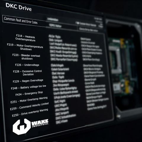
Even with a proper setup, you may encounter faults or error codes on Indramat DKC drives during commissioning or operation. The DKC drives use a two-letter or four-character code system on the 7-segment display (and in DriveTop) to indicate status and errors. Understanding these codes is key to troubleshooting. Here are some common faults, what they mean, and tips to resolve them:
Fault vs. Warning Codes:
DKC diagnostic messages are classified as “Fault” or “Warning”. Fault codes start with “F” followed by a number, and generally indicate a fault condition that has caused the drive to shut down or stop the motor. Warning codes start with “E”, and indicate a non-fatal issue that may require attention but hasn’t stopped the drive yet. For example, an E250 Drive Overtemperature Warning might prelude an F218 Overtemperature Shutdown if the condition persists. If multiple messages occur, the drive shows the highest-priority one. An error takes priority over a warning. Tip: It’s normal to see an AF code when all is OK (drive ready), and brief codes like UL or PL during resets or parameter loading. Anything starting with F or E, however, deserves investigation.
Overtemperature Faults:
Two of the most common error codes are F218 and F219, which refer to overtemperature conditions. F218 – Heatsink Overtemperature Shutdown means the drive’s internal heatsink exceeded its max allowed temperature and the drive has shut down to protect itself. Check that the drive’s cooling fans are working (if present), the heat fins are clean, and the cabinet ambient temperature is within spec typically not above 45–55 °C. Ensure there is sufficient ventilation or external cooling for the drive. F219 – Motor Overtemperature Shutdown indicates the motor’s temperature sensor tripped the limit. This could be due to heavy load, inadequate motor cooling, or a miswired temperature sensor. Allow the motor to cool and consider reducing the duty cycle or check the motor’s blower, if it has one. Both of these faults have corresponding warnings E250 for drive overtemp, E251 for motor overtemp that appear before shutdown; if you catch those warnings you can proactively reduce load or improve cooling to avoid a trip.
Excessive Deviation / Following Error:
F228 – Excessive Control Deviation means the motor’s actual position or speed deviated too far from the commanded value. In other words, the following error exceeded the fault threshold. This often occurs if the axis is blocked or jammed, if the acceleration commanded is beyond what the tuning can handle, or if the servo gains are too low. If you get an F228, first ensure the mechanical axis is free and not hitting a hard stop. Next, consider increasing the following error limit parameter if it’s too tight for normal operation. But also revisit tuning: a well-tuned servo will rarely throw F228 unless something is wrong. This fault can also happen during auto-tuning if the test move was too aggressive – in that case, you might need to manually tune or verify the inertia setting.
Emergency Stop:
F434 – Emergency Stop is triggered when the drive’s E-stop circuit is opened. Essentially the drive received a shutdown signal often via a hardware input or a SERCOS bus command that corresponds to an emergency stop condition. When this happens, the drive will remove power to the motor or decelerate it depending on configuration and post F434. To resolve, you need to reset the E-stop condition, release the E-stop button so the safety circuit is closed and then reset the fault press S1 or send a reset command. It’s important to confirm that it was indeed a user-hit E-stop and not an intermittent wiring issue on the safety chain.
Undervoltage / Power Faults:
Errors in the F2xx range can also include DC bus issues. For example, F226 – Undervoltage means the DC bus dropped below the minimum level. This can happen if the mains power supply is lost or dips while the drive is enabled, or if an external bleeder resistor or power supply issue occurred. Check the incoming AC power and any supply modules feeding the drive. Another related one is F229 – Regen Overvoltage happens if too much energy is fed back and the bus capacitors overcharge. The DKC drives typically have internal regen resistors, but high inertia decelerations might require an external resistor. If you see overvoltage faults, consider installing or checking the regen resistor and decel rates.
Feedback and Encoder Errors:
The DKC will throw faults if it detects an encoder problem. For instance, F212 or F213 might indicate encoder signals out of range, and F214 could indicate a broken wire to the feedback device (exact codes can vary by firmware). Also, F2xx faults classified as “non-fatal” might occur for minor issues that still decelerate the drive. If you see an encoder error, inspect the feedback cable for damage or loose connections, and ensure the encoder type parameter matches the actual encoder. Sometimes simply reseating the connector fixes these.
Communication and Interface Errors:
Codes in the F4xx range relate to interface issues. For example, losing a SERCOS sync or a fieldbus connection can trigger an interface fault. An F404 or F416 might indicate a SERCOS ring break or phase failure. Check fiber optic cables and that the controller is properly communicating. A F403/F421 could indicate a Profibus or CAN bus error such as duplicate node address or bus-off condition. Resolving these typically involves addressing the network communication problem (correct the address, replace a bad cable, etc.).
Low Battery Warning (F248 / E248):
If your servo motor has an absolute encoder with a backup battery (common in multi-turn absolute encoders), the drive monitors the battery status. F248 – Battery voltage too low is a non-immediate fault indicating the encoder backup battery is nearly dead. The solution is to replace the battery promptly – usually located in the motor end cap or sometimes connected to the drive. After replacing, reset the fault. If the battery was completely dead, you might need to re-reference the axis since absolute position could be lost.
When a fault occurs, the first step is always to remove the cause and then reset the drive. Many faults can be reset by cycling the drive enable or using the S1 reset button (momentarily) once the issue is fixed. However, do not repeatedly reset without addressing the root cause – for instance, if an F218 keeps happening, you risk damage if you just reset and run without cooling. Use the DriveTop diagnostics buffer to see a log of the last several errors, which can help if the fault is intermittent.
Bosch Rexroth documentation provides extensive fault code lists. As a rule of thumb: “F” faults bring the drive to a halt for safety (torque is usually cut to zero or the drive goes into a controlled stop depending on the fault class), whereas “E” warnings allow the drive to continue running but they should not be ignored. Some common warnings include E251 Motor Overtemp Warning, E259 Command Velocity Limited (which just informs that a software velocity limit is capping the speed), and E829/E830 Positive/Negative end limit reached which occur right when hitting a travel limit. These warnings, if unaddressed, often precede a full fault.
Troubleshooting tips:
Always start by reading the error code and its descriptive text. For example DriveTop will show a text like “Heatsink Overtemp” next to the code, and the DKC manual has a description and remedy for each code. The code format often hints at the category: F2xx are non-fatal or feedback issues, F4xx interface, F6xx travel limit, F8xx fatal immediate shutdown.
Many issues can be solved by proper parameter setting: if you get F607 Position Limit Exceeded (or E829/E830), maybe you need to increase the soft travel range in parameters because the machine’s required motion is larger than the default.
If the drive refuses to enable, check the drive enable input circuit. Some DKC drives have an input that must be pulled high/low to enable the power stage. If that circuit is open, the drive stays in “drive lock”. This might not throw a fault, just remains off (BE or similar status code). Wiring the proper jumper or PLC output to the enable signal will fix it.
When in doubt, power-cycle the drive. Some faults, once latched, will not clear until power is removed and restored, especially those involving internal hardware. Just be sure the motor is safe to be de-energized.
Indramat DKC drives are designed to be robust, and error codes are there to protect the system. By systematically addressing the cause of each fault and consulting the manual’s troubleshooting guide, you can usually get the drive back to operation without extensive downtime.
Wake Industrial offers expert solutions from our experienced technicians, provide any and all relevant fault codes when getting in contact with a Wake Industrial representative. To get in contact with Wake Industrial, call 1-919-443-0207 to receive a quote and to learn more about our repair options.
Safety Considerations During Programming and Commissioning
Programming and commissioning servo drives involve working with high-power electrical equipment and moving mechanical parts, so safety is paramount. Here are key safety considerations when working with Indramat DKC drives:
Electrical Safety:
DKC drives operate with dangerous voltages often 3-phase AC 380–480 V, and DC bus levels up to ~700 V on larger units. Always ensure power is disconnected and locked out before wiring or connecting/disconnecting any cables. Capacitors in the drive can stay charged even after power is off – wait the recommended discharge time and verify voltage with a meter. Never touch live terminals . Only the control connectors (0–50 V signals) are safe low-voltage circuits, and even those should be handled with care to avoid short circuits. Use insulated tools and wear appropriate PPE when working inside control cabinets.
Mechanical Safety – Moving Parts:
When you enable a servo drive, the connected motor may move unexpectedly if the parameters or controller signals are not as intended. Secure the mechanics of the system before tuning or testing. If it’s a linear axis, make sure it can’t run into end stops or people; if it’s a rotary axis, ensure nothing is attached that could become a projectile. Keep a safe distance from the motor and driven machinery during tests. Always have a quick way to hit an Emergency Stop to remove power if the axis starts to run away or oscillate. Use the buddy system – have someone ready to cut power if you’re tuning an unpredictable system.
Securing Vertical Axes:
A special case is vertical axes or any axis that can fall due to gravity. Never rely solely on the motor’s holding brake or the drive’s torque to hold up a vertical load during maintenance. The motor brake is not sufficient to guarantee the safety of personnel on its own. Always use external safety supports or clamps when working on a vertical axis. For example, if you have a Z-axis on a machine, block it or support it with a mechanical stop before disabling the drive for parameter changes. When powering up, be cautious – if parameters are wrong, the axis could drop before the drive catches it.
Proper Grounding and Noise Prevention:
Ensure the drive and motor are properly grounded. Grounding is not just for noise reduction, but also for safety to prevent any touchable surfaces from rising to a dangerous potential. Use the designated ground terminals on the drive and the motor chassis ground. A floating ground can be a shock hazard and can also cause erratic drive behavior or damage. Additionally, route power and signal cables according to guidelines separate power and feedback cables, use shielded cables for encoders and analog signals with the shield grounded at the drive end to prevent electromagnetic interference which could cause unintended motion or faults.
Parameter Changes and Test Moves:
When adjusting parameters that affect motion, do so in small increments. For instance, doubling a velocity gain suddenly could make the axis jump or oscillate violently. Increase values gradually and test in a controlled manner. Utilize software “simulation mode” or disable the power stage if the drive has that feature while you change parameters, then enable testing. Many drives have a “safe mode” or can be put in a mode where the power stage is off but feedback is live – use this to verify feedback signals you can rotate the motor shaft by hand and see encoder counts without powering the motor. This prevents accidental motion during setup.
External Safety Devices:
Do not rely solely on the drive’s fault reaction for safety. Integrate the DKC drive into the machine’s safety circuit. That means E-stop buttons, safety interlocks, limit switches, and firmware safety functions should all be employed. For example, have hard-wired overtravel limit switches that cut power or inform the drive to stop, in addition to the software travel limits in the drive. Use an appropriate safety relay or PLC so that if a drive fault occurs, other parts of the system know about it and stop accordingly. The DKC drive can provide a fault contact output – make sure to wire that to your master control as needed so an F fault can e.g. drop a control relay to other axes.
During Commissioning:
Keep the drive in local mode (DriveTop) only for as long as needed to set it up. Once you integrate with the main control, don’t leave the DriveTop session active and try to control the drive. Conflicting commands from PC and PLC can be dangerous. Always coordinate so only one control source is active at a time. When you finish programming, close the DriveTop or set it to monitor-only mode, and let the PLC or CNC take over commanding the drive.
Thermal and Environmental Safety:
Drive controllers can get hot during operation. Avoid touching the housing or heatsink shortly after operation – it could cause burns. Provide proper panel cooling to keep the temperature within spec. Also, ensure no conductive debris falls into the drive – that could cause shorts and violent failures on power-up. Keep the area around the drive clear of unnecessary items, and never cover the drive’s ventilation slots.
In essence, treat a servo drive system with the same caution you would a powerful, automated machine – because it is one. Follow all the manufacturer’s safety instructions and your facility’s safety protocols. By planning for the worst-case movements and maintaining a vigilant stance during testing, you can commission the DKC drive without incident. Safety is not just about avoiding injury, but also preventing equipment damage – a runaway axis can wreck a machine. A careful, methodical approach to programming will keep both you and your machine safe.
Integration with PLCs and Factory Automation Systems
Integrating the Indramat DKC drive into a broader automation system is often the end goal of commissioning. Whether you are connecting the drive to a PLC, a dedicated motion controller, or a CNC system, you’ll want the DKC to work seamlessly as part of the whole. Here are some considerations for integration:
Choosing the Control Mode:
As covered in the communication section, decide if the drive will be handling position control internally or if an external controller will close the loop. For instance, if you have a PLC with motion control capabilities, you might use the DKC in velocity mode (PLC sends speed or position commands). On the other hand, if the DKC is the primary controller for the axis (like in a point-to-point indexing conveyor), you might configure and trigger its internal positions via PLC I/O. The DKC series is flexible – for example, the DKC01.1 can act as a position controller on its own or accept analog speed commands, or even behave like an electronic gearing. The integration setup will differ: in stand-alone mode you wire more I/O, in networked mode you send commands over the bus.
PLC Programming and Signals:
If using a PLC, incorporate the DKC’s signals into your PLC program. This includes drive enable signal, drive ready status, fault status, and possibly homing or limit signals. Typical logic: the PLC energizes an output to enable the drive, monitors a drive “ready” bit before issuing motion commands, and if a fault bit comes, the PLC logic triggers an alarm and halts the sequence. If over fieldbus, these signals come as part of the status word and control word for example, in Profibus or CANopen DS402, you have a standardized control word to enable the drive and a status word that indicates Ready/Fault states.
Synchronization and Coordination:
In multi-axis systems, ensure that all drives share a common motion reference if needed. For SERCOS, this is inherent; for CANopen, you might use the sync messages; for analog, ensure the controllers update outputs synchronously if needed. The goal is to coordinate moves reliably. DKC drives can handle being part of electronic line shafts or print register controls – but the setup of ratios or cam profiles would be done in the controller that supervises them.
Using Drive Internal Programs:
Some versions of DKC firmware allow storing simple programs or motion profiles. If your application is simple like move to position A, then B, then back to A repeatedly, you can program those positions in the drive’s memory and trigger them via digital inputs or fieldbus commands, rather than continuously streaming commands from a PLC. This reduces bus traffic and can increase reliability. For example, you might configure block 1 = 1000 mm, block 2 = 0 mm, and then just flip a bit to execute block 1 or 2. The DKC will handle the acceleration and deceleration defined for those moves. This is an optional feature, but worth noting if offloading motion from the PLC is desirable.
HMI and Diagnostics Integration:
Provide a way for operators or maintenance personnel to see drive status from the main HMI. This could be as simple as mapping the DKC fault code to a descriptive alarm on the HMI. Also, consider integrating a remote reset. If the machine’s safety standards allow, you might have an HMI button that triggers the drive’s reset (S1) via a digital output or fieldbus command – this can save time so that minor faults can be cleared without opening the cabinet. However, only implement this if you are confident it won’t lead to unsafe restarts.
Preventive Monitoring:
Leverage the drive’s diagnostics for preventive maintenance. For example, some DKC drives count operating hours or thermal cycles. A PLC can read these and raise a flag when thresholds are reached. Also monitor motor load or torque usage in normal operation – if you see a trend of increasing torque for the same motion, that might indicate mechanical wear.
Safety Integration:
If your system has a safety PLC or safety relays, integrate the DKC in the safety schema. While the drive itself can handle safe torque off when E-stop is hit, in higher safety categories you might use an external safety relay to cut power contactors feeding the drive. Ensure that when the safety system is triggered, the drive’s controller knows about it so it doesn’t keep trying to command the drive. For SERCOS, safety can be integrated at the controller level. For simpler systems, the hardwired E-stop and drive enable wiring is the integration point.
Finally, if you’re retrofitting a DKC drive into an existing automation line, check compatibility: DKC drives can often be replaced for older Indramat units, but you may need to adjust interface wiring or PLC configurations. For example, if replacing an analog drive with a DKC, you might need to provide the DKC with an enable signal that the old drive didn’t require. Wake Industrial has a wide berth of knowledge regarding the repair and replacement of DKC drives - fill out the quote form or call us at 1-919-443-0207 to get the support you need.
Integration is successful when the drive behaves like an invisible part of the whole machine – it should respond to commands and feed back status in a way that the rest of the system can understand easily. Indramat DKC drives, once programmed and tuned, generally require little intervention. They will run under the command of your PLC/CNC day in and day out, and you can focus on the high-level control, only delving into drive parameters if something changes like a new product recipe requiring tuning adjustments, or a component replacement. In summary, tie the DKC into your automation system via the appropriate interface, program your PLC or controller to manage it with the proper handshaking and safety checks, and the drive will reliably execute the motion tasks that you’ve configured it for.
Update: Checkout our series review of the DKC Product Line
Conclusion
Programming Bosch Rexroth Indramat DKC series drives may seem complex, but by following a structured approach – from wiring and initial parameter setup through tuning and integration – even legacy Indramat drives can be made to run like new. We’ve covered how to connect and configure the drive, adjust its parameters for your motor and application, use DriveTop tools for tuning the servo loops, and troubleshoot common issues using fault codes and best practices. With the DKC drive properly programmed, your servo system will deliver precise and efficient motion control for years to come.
If you need immediate assistance with your DKC drive, call Wake Industrial at 1-919-443-0207 to receive immediate assistance. Our team of technicians are ready to assist you with your repair order, ensuring you receive the support you need without any hassle or rush fees. Please have your part number and your fault code identified to ensure expedient service.
"Wake Industrial is sharing information sourced from the original manufacturer's manual. Please be advised that Wake Industrial does not offer troubleshooting assistance through phone or email. For repair, replacement, or refurbishment needs, we invite you to use our quote form or call us at 1-919-443-0207. It is the user's responsibility to exercise independent judgment and caution when implementing these instructions. Wake Industrial shall not be held liable for any direct, indirect, incidental, or consequential damages to products or individuals resulting from the use of this information."
Request a Quote
Cary, NC 27513


