


Request a Quote
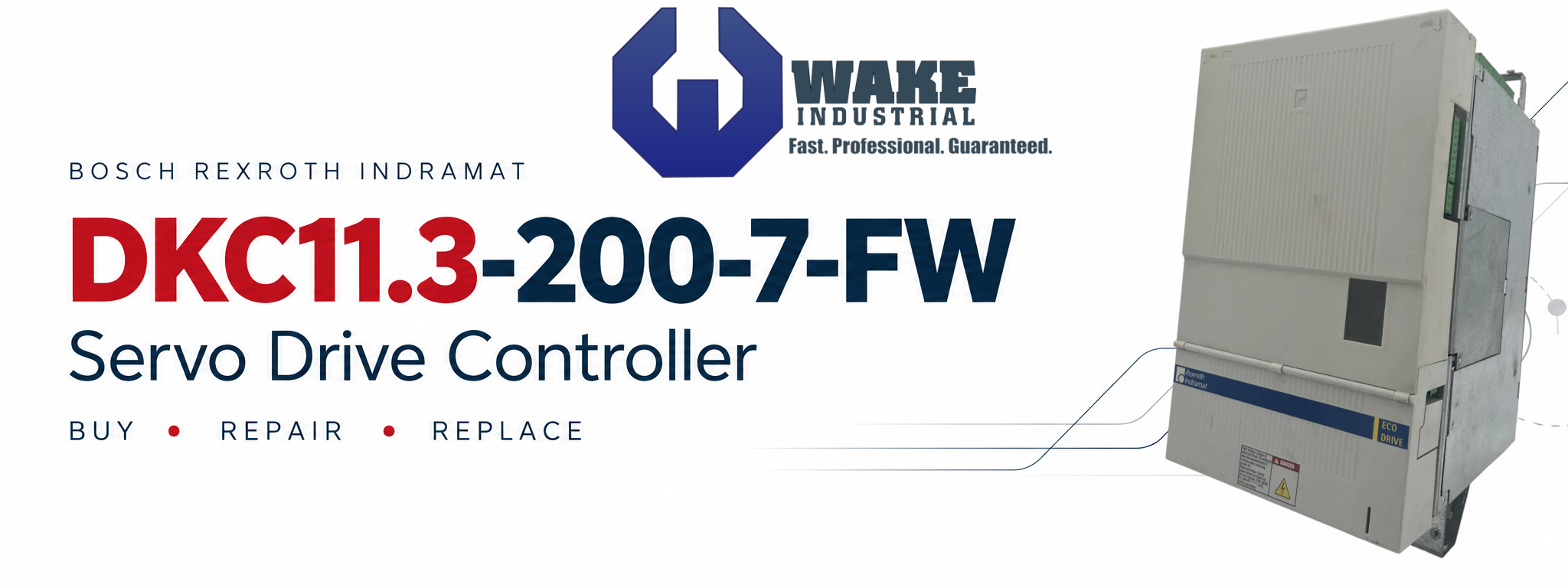
Bosch Rexroth DKC11.3-200-7-FW Servo Drive Controller
Looking for a fast quote on repair or refurbishment of your DKC11.3-200-7-FW? Contact Wake Industrial directly at 1-919-443-0207 or use the quote form embed on this page to receive a quote within 15 minutes. The Bosch Rexroth Indramat DKC11.3-200-7-FW is an EcoDrive drive controller with a 200 A type-current designation that is part of the DKC Drive Controller series.
The controller combines motor-power connections, encoder interfaces, machine I/O, and diagnostic functions within the EcoDrive platform. Its programming module separates unit firmware from application parameters, making both important when replacing a failed drive. Matching the hardware designation, motor feedback, and saved machine settings helps prevent a replacement from introducing configuration problems into an otherwise serviceable system.
DKC11.3-200-7-FW Technical Overview
The DKC11.3-200-7-FW uses separate connections for control power, motor power, feedback, and machine signals. A 24 VDC supply powers the control circuits through X1, while X5 provides the mains, motor, and DC-bus connections. This separation matters during fault diagnosis: an active display confirms that the control electronics have power, but does not by itself establish that the motor-power circuit is ready.
Specifications | Detail |
Manufacturer | Bosch Rexroth Indramat |
Product family | EcoDrive 03 drive controllers |
Series and version | Series 11, version 3 |
Type-current designation | 200 A |
Control supply | 24 VDC through X1 |
Serial connections | RS-232 and RS-485 at X2 |
Machine I/O | Digital and analog inputs and outputs at X3 |
Encoder connections | Encoder 1 at X4; encoder 2 at X8 |
Motor monitoring and brake connections | Motor temperature monitoring and holding-brake connections at X6 |
Programming module | X7, incorporating parameter modules |
Local diagnostics | H1 diagnostic display and S1 reset key |
Common ECODRIVE03 Fault Codes and Checks
Record the complete diagnostic code and the operating condition when it appears. Electrical inspection and corrective work should be performed by qualified personnel with the equipment safely isolated.
Fault | Meaning and typical symptom | Checks to prioritize |
F218 | Amplifier overtemperature shutdown; the drive trips as its heatsink becomes too hot | Check cabinet temperature, heatsink contamination, airflow restrictions, and blower condition |
F219 | Motor overtemperature shutdown; operation stops after excessive motor heating or a temperature-signal problem | Check sustained mechanical loading, increased friction, temperature-monitor wiring, and velocity-loop settings |
F220 | Bleeder overload shutdown; a trip can occur during energy-intensive braking | Review speed and deceleration demands, returned energy, braking capacity, and the installed bleeder arrangement |
F221 | Motor temperature monitoring defective | Inspect the temperature-monitor circuit for an interrupted connection or short circuit |
F226 | Undervoltage in the power section; the drive shuts down when DC-bus voltage falls too low | Check the power supply and whether mains power is being removed while drive enable remains active |
F228 | Excessive deviation; the axis cannot follow its commanded position within the monitoring window | Check for mechanical binding, excessive acceleration, torque limits, control-loop settings, and monitoring-window settings |
F229 | Encoder 1 quadrant error; incorrect encoder signals are detected | Inspect the encoder cable, interference exposure, encoder interface, and drive hardware |