

Installing and Operating Danfoss VLT Drives: A Comprehensive Guide
29 August, 2025 | Danfoss VLT drives, VLT drive installation, Danfoss VLT troubleshooting, Install Danfoss VLT, VLT fault codes, VLT error codes, VLT drive commissioning, Danfoss VLT repair service, VLT 3000, VLT 2800, VLT 5000, VLT 6000,
Wake Industrial is sharing information sourced from the original manufacturer's manual. Please be advised that Wake Industrial does not offer troubleshooting assistance through phone or email. For repair, replacement, or refurbishment needs, we invite you to use our quote form or call us at 1-919-443-0207. It is the user's responsibility to exercise independent judgment and caution when implementing these instructions. Wake Industrial shall not be held liable for any direct, indirect, incidental, or consequential damages to products or individuals resulting from the use of this information.
Looking for the easy to read error table? Click here.
Danfoss’s VLT family encompasses several series of AC drives, each designed for different power ranges and applications. All VLT drives share common traits: compact size, high power density, and robust performance. In fact, Danfoss VLT drives are celebrated for having one of the best size-to-power ratios on the market. They are lightweight yet powerful, with built-in features like RFI filters and heavy-duty heat sinks to ensure long life and minimal electrical noise. Engineers can easily customize parameters using either the drive’s intuitive keypad or PC-based software tools, making integration and tuning straightforward. For immediate assistance with a VLT repair or replacement call Wake Industrial at 1-919-443-0207 or fill out the quote form and a representative will get back to you in as soon as 15 minutes during business hours. (Wake Industrial is not an authorized distributor).
A compact drive series for smaller motors, the VLT 2800 was a popular “micro-drive” range. These units covered low-power applications across common supply voltages. Despite their small footprint, VLT 2800 drives offered rich functionality like adjustable ramp times and motor overload protection. They could be mounted side by side in control panels (thanks to the book-style design) and included integrated RFI filters to minimize electromagnetic interference. Note that the VLT 2800 is now discontinued and in the Inactive lifecycle phase.
VLT 3000 Variable Speed Drives:
The Danfoss VLT 3000 variable speed drives were a broad range covering from very small 0.5 HP units (model 3002) up to much larger drives (model 3250) for higher horsepower needs. This series used pulse-width modulation (PWM) technology to convert incoming AC to DC and then to a variable-frequency AC output for precise motor control. The efficiency of VLT 3000 drives was around 96% at full load, with near unity power factor (0.9–1.0) depending on model and conditions – excellent performance that meant minimal energy waste. They supported multiple supply voltages: 200–230 V for smaller motors, 380–415 V for standard industrial power, and 440–500 V for higher-power systems. The drives were built to thrive in industrial environments, with operating temperature ratings from -10°C up to +45°C at full load. Various enclosure ratings were available (from basic NEMA 1/IP21 up to NEMA 12/IP54) to suit different environmental demands. Standard features on the VLT 3000 included built-in RFI filters and DC chokes to reduce harmonic distortion and electromagnetic interference. The control electronics provided configurable parameters such as acceleration/deceleration ramps, current limits, and an electronic thermal relay to protect the motor. In short, the VLT 3000 series was a workhorse line of drives used across industries for many years.
VLT 5000 Frequency Converters:
The VLT 5000 was Danfoss’s flagship general-purpose drive series in its time. These drives covered a very wide power range – roughly from 0.75 kW up to 355 kW, across various voltage classes (200–240 V, 380–500 V, and 525–600 V). In other words, a single VLT 5000 series could be applied to almost any industrial motor, from small pumps to large heavy-duty machinery. The compact form factor was a major selling point: even high-power models came in a book-style design to save valuable cabinet space. The VLT 5000 drives also excelled at energy savings, using precise speed control to match motor output to the actual load demand – thereby reducing excess energy usage. They featured user-friendly operation; Danfoss provided a unified interface such that if you learned one VLT drive, you could operate others easily. A built-in Quick Menu guided users through the minimal programming steps needed to commission the drive for a new application.
The VLT 6000 was a specialized variant of the VLT family, designed specifically for HVAC applications. These drives introduced features that building engineers and facility managers appreciate – for instance, easy integration with building management systems and optimized control for fans and pumps. A VLT 6000 HVAC drive provides very precise regulation of parameters like air flow, water pressure, and temperature in HVAC systems, resulting in superior environmental control and significant energy savings for large buildings. In practice, installing VLT 6000 drives in a facility allowed building owners to maintain comfort levels while cutting energy costs, thanks to variable speed control of chillers, cooling tower fans, air handlers, etc.. The VLT 6000 came in a range of sizes and often included conformal coated electronics for reliability in ventilation plant rooms.
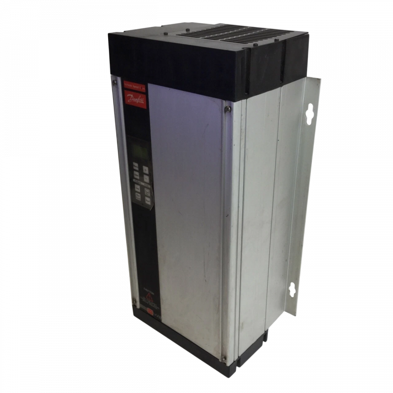
The Danfoss 175H7240 is part of the VLT 3000 Variable Speed Drives series, offering an output power of 1.1 kW and a programmable output frequency range of 0–120 Hz or 0–500 Hz
Installation Steps for Danfoss VLT Drives
Proper installation is crucial for the safe and reliable operation of any VFD. Danfoss VLT drives are designed to be installer-friendly, with features like modular mounting and software tools to aid setup. If you’re a new user, follow these general installation steps:
- Planning and Safety: Before beginning, review the drive’s manual and safety instructions. Verify that the drive’s specifications (voltage, current, enclosure rating) match your application and environment. Plan the installation site with adequate clearances for cooling airflow and maintenance access. Ensure the ambient temperature will stay within the drive’s allowable range. Always disconnect power and lockout/tagout the supply before wiring the drive.
- Mounting the Drive: Physically mount the VLT drive in your electrical panel or designated location. The book-style design of Danfoss VLT drives allows for side-by-side mounting without extra space in between. Use the provided mounting holes or brackets to secure the unit vertically. Ensure the drive is mounted on a vibration-free surface. For higher IP rated enclosures, make sure all gaskets and seals are in place to maintain the ingress protection. Tip: If installing multiple drives, consider panel cooling and possibly use external fans or air circulation, since multiple VFDs in one cabinet can generate significant heat.
- Power Wiring: Connect the AC supply to the drive’s input terminals (usually labeled L1, L2, L3). Use appropriately sized copper conductors as specified by the manual and follow all local electrical codes. It’s recommended to install a dedicated circuit breaker or disconnect and fuses upstream of the drive for protection. Connect the motor leads to the drive’s output terminals (usually labeled U, V, W). Important: proper grounding is essential – bond the drive’s ground terminal to the system ground. Danfoss VLT drives come with internal RFI filters to reduce noise, but you should still use shielded motor cables with the shield grounded at the drive end to minimize electromagnetic interference. After making connections, double-check that terminals are tight and that no stray wire strands are shorting. Many VLT units have removable wiring access plates or knockouts for routing cables; ensure any covers or plates are reattached after wiring is complete. For example, the VLT 3000 drives have bottom cable entry plates that must be put back in place after installation – if left off, the drive’s cooling airflow will not be directed correctly and performance could suffer.
- Control Wiring: Next, wire any control and signaling connections. This may include connecting start/stop commands, analog input for speed reference, digital inputs for safety interlocks, or fieldbus communication cables if the drive is networked. The VLT drives typically have a control terminal strip for low-voltage signals. For simple installations, at minimum you will need to wire a Start/Stop circuit (or enable switch) and a speed reference. Ensure all control wiring is run separate from power cables to avoid noise coupling. If using an external keypad or remote panel, connect it according to the manual. It’s good practice to test any safety interlock or “E-Stop” circuits at this stage.
- Initial Power-Up and Parameter Setup: Once wiring is done and covers are in place, you can power on the drive. The drive’s display (or LEDs) should illuminate, indicating it’s ready for programming. Danfoss VLT drives make parameter setup easy – if you’re familiar with one model, the menu system is consistent across the series. Most VLT drives include a Quick Start or Quick Menu mode to input basic parameters. Begin by entering the motor nameplate data: motor voltage, motor power or current, motor frequency, and motor nominal speed. Setting these correctly is critical for the drive’s performance and protection of the motor. The drive may also prompt you to choose a control mode or torque characteristic. For example, select “Constant Torque” vs “Variable Torque” depending on your load type. In fact, if using a VLT drive with parallel or multiple motors, Danfoss recommends selecting the constant torque mode to ensure stable operation. You can then set the acceleration and deceleration ramp times, any preset speeds, and min/max frequency limits as needed for your application. The VLT’s Local Control Panel (LCP) has an LCD display and keypad for this purpose, making it straightforward to navigate through parameter groups. Alternatively, Danfoss provides PC software (like MCT 10 or older software tools) which you can use to connect to the drive for configuration – all VLT drives support PC-based parameter editing if that’s more convenient.
- Testing and Commissioning: With parameters set, test the drive in a safe manner. Keep the motor disconnected from any mechanical load for initial testing if possible. Give a start command at low frequency and verify the motor turns in the correct direction. Observe the drive’s display for any fault or warning codes during startup. Gradually ramp the speed up and down to ensure smooth acceleration and deceleration. Also test the stopping method. If the drive will be controlled remotely, switch it to external control mode and confirm it responds correctly to the control signals. Finally, monitor the motor current draw and compare to expected values – this can catch issues like an incorrect motor parameter or an excessive mechanical load. Once everything looks good, you can couple the motor to the load and do a full-speed test in the actual system. Be sure to document the parameter settings and back them up This completes the installation and basic commissioning.
By following the above steps, new users should be able to install a Danfoss VLT drive with confidence. Always refer to the official Danfoss installation guide for your specific model if in doubt, and heed all safety warnings.
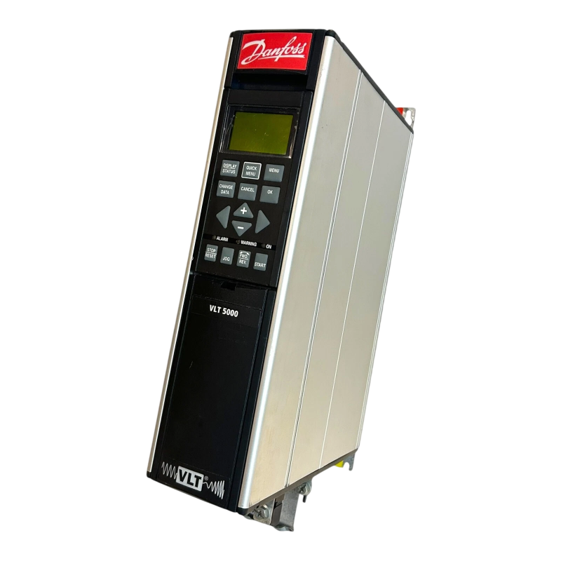
The Danfoss 175Z0047 is part of the VLT 5000 Frequency Converters series and features a power rating of 2 HP with a three-phase configuration.
Operating and Monitoring VLT Drives
After installation, day-to-day operation of Danfoss VLT drives is relatively straightforward. Operators can start, stop, and adjust speed either through the drive’s interface or via a connected control system. The local keypad on VLT drives typically allows manual control for testing or local override – you can scroll through menu displays to read out status information such as output frequency, motor current, voltage, temperature, etc. The display also shows any active warnings or alarms in plain text or code, which is vital for troubleshooting.
For integration into automated systems, VLT drives support a variety of control interfaces. Many units have terminals for analog inputs and digital inputs. They also can be equipped with fieldbus modules for networked control – this is common in modern plants where a PLC sends commands to the drive. Danfoss made sure that if you know one VLT drive, you know the others – the parameter structure and function codes are consistent, which reduces the learning curve for operators.
Monitoring your VLT drive’s performance is important for maintenance. Check periodically that the drive’s cooling system is working. The built-in heatsink and fan are designed to keep the drive electronics below critical temperature, but dust or obstructions can impede cooling. Many drives will give a temperature warning if they’re running hot. When your machine begins to fail and it's time to replace it, contact Wake Industrial via sales@wakeindustrial.com to get a quick quote for your VLT replacement.
Troubleshooting Tips for VLT Drives
Even with a solid installation, you may occasionally encounter trips or performance issues with your VLT drive. Troubleshooting involves a mix of interpreting the drive’s alarms and systematically checking external factors. Here are some tips and common issues:
|
Alarm / Fault |
Cause |
Solution / Action |
|
Overcurrent (Alarm 13) |
Drive output current exceeded safe limit (e.g., >200% rating). Causes include rapid acceleration, motor overload/jam, or output short circuit. |
Check for mechanical binding or overload, increase ramp-up time, verify motor parameters (especially impedance), inspect motor cable for shorts. |
|
Earth Fault / Ground Fault (Alarm 14) |
Current leaking to ground due to short in motor winding/cable insulation. May also be caused by moisture, dust, or long cables without proper grounding/filtering. |
Test motor & cable with megohmmeter, clean motor terminals, inspect insulation, check grounding. Treat genuine alarms seriously. |
|
Over Temperature (Alarms 29, 65, 66) |
Drive overheats due to blocked airflow, failed fan, dusty heatsink, or high ambient temperature. Can also happen if drive is undersized for load. |
Check cooling fan & heatsink, clean filters, improve ventilation, verify ambient temp rating, resize drive if overheating persists. |
|
Missing Motor Phase (Alarms 30, 31, 32) |
One motor phase open (U, V, or W). Could be broken wire or winding failure. |
Inspect wiring motor terminals, measure winding resistance (all phases should be similar). |
|
DC Link Voltage Alarms (Alarm 7 = Over-voltage, Alarm 8 = Under-voltage) |
Over-voltage: supply surge or regenerative braking without resistor. Under-voltage: supply dip or missing phase. |
For Alarm 7: check supply voltage, add brake resistor if needed. For Alarm 8: verify stable input supply, check fuses/phases. |
|
External Interlock / Safety Shutdown (e.g., Alarm 60) |
Open safety chain (E-stop, door switch, external interlock input not energized). |
Inspect safety circuits, verify 24V on interlock input, reset alarm after restoring circuit. |
Conclusion: Maximizing the Value of VLT Drives
Danfoss VLT drives have earned a strong reputation in industrial automation for their durability, performance, and rich feature set. From the versatile VLT 5000 that could handle virtually any application to the specialized VLT 6000 HVAC that optimized building climate control, these drives have contributed significantly to energy savings and process improvements over the years. By following proper installation practices and leveraging the built-in diagnostics, engineers and plant owners can ensure these drives operate at peak efficiency. The technical details – from high power factor operation to integrated filters and protections – all play a role in reducing downtime and operating cost for businesses.
However, as with any technology, maintenance and eventual replacement are part of the life cycle. Many VLT drives are now discontinued by the manufacturer, but that doesn’t mean they must be scrapped at the first sign of trouble. With a knowledgeable approach to troubleshooting and the availability of third-party support, you can often repair or refurbish a faulty drive and gain years of additional service. Wake Industrial offers a convenient avenue to buy hard-to-find VLT drive units or repair your existing drives when they falter. Just call 1-919-443-0207 or email sales@wakeindustrial.com to get a comprehensive and competitive quote from Wake Industrial.
Request a Quote
Cary, NC 27513


