


4.95 based on 202 reviews

🙶 I have always received exceptional service and support in my many years of working with Wake Industrial. 🙷

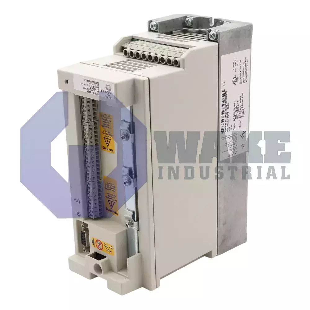
10.F5.C1B-3A0A KEB

No Tariffs On US Orders
  • Rated 4.6 (63 total ratings)
  • Straightforward Pricing: No Rush Fees, No Credit Card Fees
In-Stock, Ships Today

Current response time:
4 Minutes 38 Seconds

Preparing your secure checkout page...

The KEB 10.F5.C1B-3A0A is part of the F5 Combivert Axis Drives series and supports three-phase input with a nominal voltage of 400 V. It features 8 digital inputs, 2 analog inputs with 12-bit resolution, and has a maximum motor power of 3 HP. The drive comes in an IP20 enclosure, has a maximum current of 12.5 Amps, and is equipped with a braking transistor.

Quote Request Form:

Warranty
Wake Industrial Warranty

To contact sales for pricing and lead time:

Payment Methods

Visa
Mastercard
AmEx
Wire Transfer

Shipping Methods

DHL
UPS
FedEx
Freight

Our Credentials

Cary Chamber
DUNS Registered
SAM Registered
BBB Accredited

Product Description:

The 10.F5.C1B-3A0A is an AC axis drive manufactured by KEB within the F5 Combivert Axis Drives series. Intended for three-phase supplies, the inverter adjusts motor speed and torque to match process demands in conveyors, winding systems, and general automation. By modulating output frequency and voltage, it serves as the intermediary between a line feeder and the mechanical load, allowing coordinated motion profiles and reducing energy usage across multi-axis machines.

This model is fed from a three-phase mains at 400 V, and its control electronics are housed in an IP20 enclosure that requires installation inside a protective cabinet. The power section can deliver up to 12.5 A of output current for short duration peaks, while continuous operation is limited to 5.8 A to keep semiconductor temperature within limits. Pulse-width modulation is executed at a carrier frequency selectable up to 16 kHz; the factory nominal setting is 8 kHz to balance acoustic noise and switching loss. Drive-side data exchange completes in 2 ms, matching the I/O scan time needed for tight PLC loops. Two unipolar analog inputs permit speed or torque references, and an integrated braking transistor dissipates regenerated energy during fast deceleration.

Mechanical layout follows KEB size code 10, giving a cabinet footprint of 90 mm in width, 220 mm in height, and 160 mm in depth so that multiple drives can mount side by side with minimal clearance. The power stage is rated for motors up to 3 HP, aligning with the 5.8 A continuous current and the built-in three-phase input topology. Eight isolated control terminals provide 8 digital inputs for run command, direction, or preset selection, while the dual analog channels accept signals with 12-bit resolution for fine reference scaling. Housing code B identifies the standard convection-cooled case, and the inverter size maintains a 2 mm² wiring recommendation to complement its switching frequencies without excessive conductor heating.


Analog Inputs
2
Analog Resolution
12 Bit
Depth
160 mm
Digital Inputs
8
Enclosure
IP20
General Max Motor Power (HP)
3
Height
220 mm
Housing
B
I/o Scan Time
2 ms
Input Phase
3-Ph
Installed Accessories
Braking transistor
Inverter Size Code
10
Max Current
12.5 A
Max Sw Freq
16 kHz
Nominal Sw Freq
8 kHz
Nominal Voltage
400 V
Product Series
Combivert F5
Rated Current
5.8 A
Width
90 mm
Error Code What it means on the keypad Typical root causes Quick fix / first checks
E.OC Over-current trip – output current or a ground fault exceeded the drive’s peak limit • Shorted motor leads• Ground fault in cable• Ramp times too aggressive• Defective contactor or output transistor 1) Megger motor & cable, repair insulation2) Bypass or replace contactor3) Lengthen accel/decel ramps
E.OP Over-voltage on the DC bus (840 V DC @ 480 V units) • Regenerative decel without brake resistor• Mains spikes / high line• Brake-chopper or regen unit mis-wired 1) Size & wire braking resistor / regen unit correctly2) Add 3–5 % line reactor3) Verify mains within spec
E.UP Under-voltage on the DC bus (< 240 V DC @ 480 V units) • Low or missing phase• Weak transformer / long cable drop• UPS mode not enabled when running on single phase 1) Measure line-to-line voltage & balance2) Inspect input fuses and wiring3) Enable UPS mode or boost supply
E.OS Overspeed ― actual RPM exceeds limit set from machine data • Wrong motor name-plate data• Encoder pole-position off• Speed-loop gains badly tuned 1) Correct LF motor parameters2) Re-learn encoder pole position3) Retune speed gains LF.31-33
E.LSF Load-shunt / charge-relay fault during power-up • Relay not pulling in (low line, bad coil)• Brake resistor on wrong terminals• Repeated brown-outs 1) Verify coil voltage & wiring2) Check PB/++ resistor wiring & resistance3) Cycle power fully; replace inverter if relay failed
E.Cdd “Error Calculate Motor Data” – motor auto-tune failed • Incorrect LF10-17 motor data• Contactor didn’t close• Motor wiring wrong phase order 1) Re-enter name-plate data, rerun learn2) Confirm contactor closes & holds3) Swap phases if rotation incorrect
E.PU Power-unit (IGBT section) hardware fault • Internal power stage failure• Noise corrupting control-to-power handshake 1) Reseat ribbon between control & power boards2) Eliminate noise sources; if fault persists send drive for repair
E.EnC1 Incremental encoder channel lost or both signals equal • Broken A/B/N differential pair• Wrong encoder supply voltage• Missing N channel not jumpered 1) Scope encoder lines, fix cable2) Jumper unused N+ / N- if TTL encoder lacks N3) Match encoder supply (5 V vs 24 V)
E.ENCC Absolute-encoder interface communication error • Bad encoder cable or card• Bent pins on interface board 1) Inspect & reseat encoder card2) Replace cable; verify termination
E.EF External fault input active / speed-following error forced external trip • X2A.10 external-fault contact closed• LF.57 set to mode 2 without jumper 1) Check external-fault wiring / PLC contact2) Install jumper between ASd output and X2A.10 or change LF.57 setting
Part Number Rated Power(kW) Line Voltage Class Nominal Current In (A) Max Current Imax (A)
10.F5.C1B-3A0A (reference) 2.2 3 × 400 V 5.8 12.5
07.F5.C1B-3B0A 0.75 3 × 400 V 2.6 5.6
09.F5.C1B-3A0A 1.5 3 × 400 V 4.1 8.9
12.F5.C1B-350A 4 3 × 400 V 9.5 21
09.F5.C1B-2B0A 1.5 3 × 230 V 7 15.1
10.F5.C1B-2A0A 2.2 3 × 230 V 10 21.6
Error code Plain-language meaning
E.OC Over-current trip (output or ground fault)
E.OP DC-bus over-voltage
E.UP DC-bus under-voltage / phase loss
E.OS Motor overspeed limit exceeded
E.LSF Load-shunt/charge relay did not pull in at power-up
E.Cdd “Calculate Motor Data” auto-tune failed
E.PU Power-unit (IGBT section) hardware fault
E.EF External fault input active
E.ENC Incremental/absolute encoder communication error
E.OH2 Electronic motor-overload protection activated

Frequently Asked Questions about 10.F5.C1B-3A0A:

Q: How many analog inputs are available on the 10.F5.C1B-3A0A axis drive?

A: This drive provides two analog inputs for external signal control.

Q: What is the rated current of the KEB 10.F5.C1B-3A0A drive?

A: The rated current for the 10.F5.C1B-3A0A is 5.8 A during normal operation.

Q: What protection rating does the 10.F5.C1B-3A0A drive's enclosure offer?

A: It features an IP20 enclosure, providing basic protection against solid objects larger than 12 mm.

Q: What accessory is installed in the 10.F5.C1B-3A0A by default?

A: A braking transistor is pre-installed in this model.

Q: What is the maximum motor power this drive can handle?

A: The 10.F5.C1B-3A0A supports a maximum motor power of 3 HP.


Internal Product Review

  • ‘‘The 10.F5.C1B-3A0A is a KEB F5 Combivert axis drive built for 3-phase, 400 V applications. Rated output at 5.8 A and an integrated braking transistor support stable motion control and dependable deceleration behavior. A 16 kHz maximum switching frequency makes this unit a strong choice for refined drive performance.’’

Motion Industries logo
3M logo
IBM logo
Gexpro Logo
Caterpillar logo
NASA logo
Ford logo
Vallen logo







