


Understanding the RAC Drive
Product Overviews23 October, 2026 | Indramat RAC drives, Bosch Rexroth RAC spindle drives, RAC main spindle controller, RAC 2 drive, RAC 3 drive, RAC 4.1 drive, Indramat RAC repair, RAC drive replacement, CNC spindle control, spindle positioning, C-axis control, regenerative braking, AS programming module, Indramat 2AD spindle motors, Indramat 1MB frameless motors
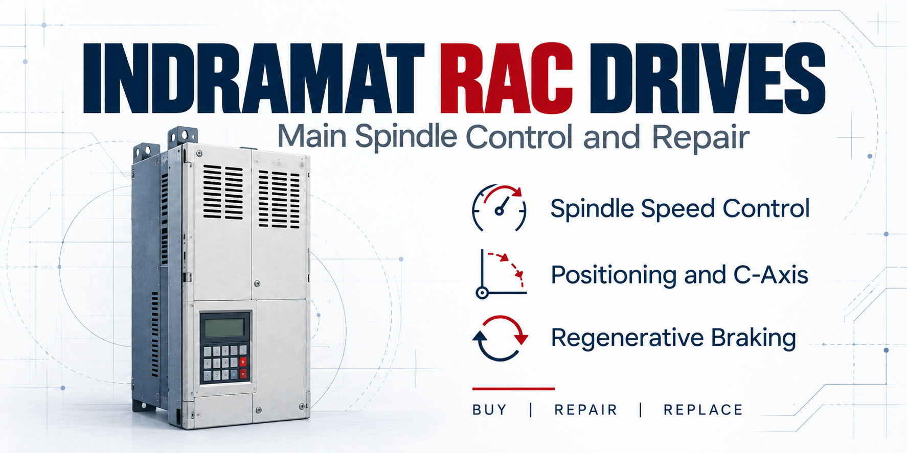
Indramat RAC drives provide digital control of main spindle motors in CNC machine tools. They combine speed regulation, spindle positioning, and regenerative braking in a controller designed to work with compatible 2AD asynchronous motors and 1MB frameless spindle motors.
The RAC platform supports more than continuous spindle rotation. With the correct feedback and control configuration, it can position the spindle at a defined angle or operate it as a controlled rotary axis. These capabilities allow one spindle system to handle different stages of a machining cycle.
Need an Indramat RAC drive repaired or replaced? Call Wake Industrial at 1-919-443-0207, email sales@wakeindustrial.com, or request a repair or replacement quote. Quotes are responded to within 15 minutes during business hours.
The Indramat RAC Drive System
An RAC spindle system consists of the controller, a compatible motor, feedback equipment, connecting cables, and an AS programming module. The controller processes commands from the machine control and uses feedback to regulate motor operation. The programming module supplies the software and parameters that adapt the controller to the motor and application.
RAC controllers connect directly to an appropriate three-phase mains supply. Their power electronics supply the motor during acceleration and cutting, then handle energy returned by the motor during braking.
The RAC 2.3-200-460-A00-W1 is one example of this architecture. Its analog speed-command configuration allows the machine control to specify the required speed while the RAC controller manages the motor’s response.
Spindle Speed Control Across a Broad Operating Range
Machining requires different spindle speeds for different tools, materials, and cutting operations. RAC drives were developed to provide high control stiffness and a broad constant-power speed range when paired with the appropriate spindle motor.
Control stiffness describes how strongly the drive resists deviations from the commanded operating condition. As the cutting load changes, the controller uses feedback to adjust motor operation. This helps maintain the requested spindle speed within the capabilities of the motor and controller.
The available performance depends on the complete drive combination. Controller current capacity, motor winding, supply voltage, and operating conditions all affect the usable output. Selecting an RAC controller therefore requires more than matching the power figure printed on a motor nameplate.
RAC 2, RAC 3, and RAC 4 Controllers
The RAC families cover different spindle power requirements. RAC 3 serves the lower power range of the three families, RAC 2 covers intermediate requirements, and RAC 4.1 supports larger spindle systems.
| RAC Family | Documented Continuous Motor Shaft Power Range | Product Example |
| RAC 2 | 30–52 kW | RAC 2.3-200-460-A00-W1 |
| RAC 3 | 10–30 kW | RAC 3.1-100-460-A00-W1-220 |
| RAC 4.1 | 52–93 kW | RAC 4.1-300-460-A00-W1 |
Spindle Positioning and C-Axis Operation
RAC controllers include an internal position-control loop that can bring the spindle to a defined angular position. This function allows the machine to orient the spindle for a subsequent operation, such as a workpiece exchange.
The feedback arrangement depends on the mechanical connection between the motor and spindle. Motor feedback can close the positioning loop on a direct-drive spindle or a system with a 1:1 transmission. Belt drives and change-speed gearing can require additional spindle feedback so the controller can determine the spindle’s actual position.
C-axis operation extends this capability by controlling the spindle as a rotary servo axis. The high-resolution feedback used by RAC systems supports the low-speed movement required for this function. Documented maximum rotor-position resolution reaches 1/4,000,000 of a revolution, although feedback resolution alone does not establish the positioning accuracy of the complete machine.
Motor and Controller Matching
RAC controllers were developed for compatible 2AD 3-Phase Induction Motors and 1MB Asynchronous motors. These motor families serve different mechanical arrangements, but both depend on correct electrical and feedback matching with the controller.
The motor-controller combination determines the applicable operating data and parameter configuration. A motor’s family name alone does not establish compatibility; its winding, feedback equipment, and complete type designation must be considered.
For an installed RAC 3.1-100-460-A00-W1-220, the motor nameplate and AS module identification provide essential information alongside the controller code. Keeping those records together makes future service and replacement selection more straightforward.
Regenerative Braking During Spindle Deceleration
When a spindle slows down, the rotating motor and load return energy to the drive. RAC controllers can feed this regenerated energy back into the three-phase supply network.
This capability is relevant to machines that repeatedly accelerate and decelerate their spindle. The controller must manage both the power needed to drive the motor and the energy returned during stopping.
Braking behavior during a mains failure depends on the RAC design and installed options. RAC 3 controllers, for example, use an optional additional bleeder for braking under this condition. The braking configuration is therefore an important part of the controller specification when sourcing a replacement.
Interfaces That Connect the RAC to the CNC
RAC controllers were offered with different command and feedback interfaces. Depending on the version, speed commands can use an analog ±10 V signal, a digital parallel interface, or SERCOS communication.
Additional options support functions such as spindle feedback, incremental encoder output, and serial communication. These interfaces connect the spindle drive to the machine’s control architecture and must be preserved when replacing the controller.
The RAC 3.5-150-460-A0I-W1-220, for example, combines an analog speed command with an incremental encoder output. The I in its interface code identifies that output. A requirement for an additional spindle-encoder input must be checked separately.
Cooling and Operating Conditions
RAC controllers use fan-assisted cooling and require a clear airflow path. Installation arrangements can circulate air inside the cabinet, draw cooling air from outside it, or use hose-cooling accessories.
Cabinet temperature and airflow affect the controller’s available performance. RAC 4.1, for example, specifies +5°C to +45°C for operation at rated data, with reduced ratings above that range up to its permitted maximum.
On a system using an RAC 4.1-300-460-A00-W1, the fan, heat sink, and air passages should be included in maintenance inspections. Restricted airflow should be corrected alongside any required controller service.
Repairing or Replacing an Indramat RAC Drive
A spindle fault can involve the controller, motor, feedback, wiring, supply, or machine configuration. Record the displayed diagnostic and note whether the problem occurs at startup, during cutting, or while stopping. Qualified personnel should evaluate the relevant external connections and operating conditions before identifying the failed component.
Replacement selection requires the full RAC type code, motor identification, AS module information, command interface, feedback options, and braking configuration. Clear nameplate photographs help preserve details that can be missed when a part number is transcribed.
Get your Indramat RAC drive repair or replacement moving today. Call Wake Industrial at 1-919-443-0207, email sales@wakeindustrial.com, or request a quote online.
Request a Quote

Cary, NC 27513