


Indramat DDS Fault Codes: Meanings, Causes, and Next Steps
Technical Error and Fault Guides18 August, 2026 | Bosch Rexroth Indramat fault codes, DDS drive error codes, Indramat DDS repair, DDS servo drive faults, Indramat H1 display codes, DDS controller troubleshooting
Looking for the easy to read error table? Click Here
Indramat DDS fault codes help maintenance teams identify problems involving the drive controller, motor, feedback device, cabling, power supply, parameters, and communication system. These diagnostic messages appear on the H1 display at the upper-right corner of the drive.
Record the complete code before cycling power or attempting a reset. If the fault repeatedly returns or indicates internal drive damage, Wake Industrial can repair, refurbish, or replace legacy Indramat DDS controllers. Call 1-919-443-0207, email sales@wakeindustrial.com, or use the form on the page to get a quote within 15 minutes during business hours.
Safety notice: This information is intended as a reference for qualified industrial maintenance personnel. Follow the machine manufacturer’s procedures, observe lockout/tagout requirements, and consult the documentation for your exact controller, firmware, motor, and installed modules. Wake Industrial does not provide technical troubleshooting support by phone or email. It is the user's responsibility to exercise independent judgment and caution when implementing these instructions. Wake Industrial shall not be held liable for any direct, indirect, incidental, or consequential damages to products or individuals resulting from the use of this information.
What Do Indramat DDS Fault Codes Indicate?
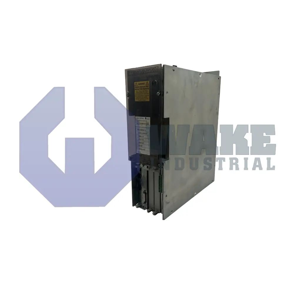
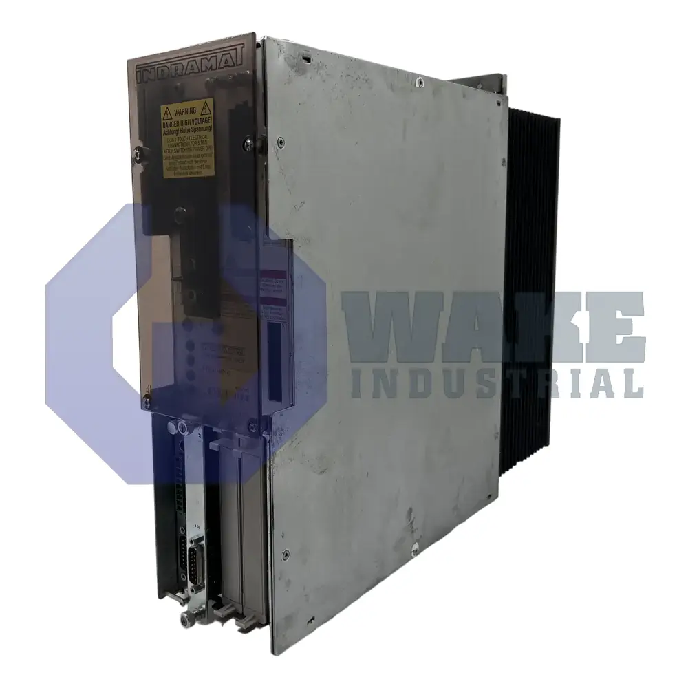
Indramat DDS Drive controllers are modular digital AC servo drives used in machine tools, printing equipment, packaging systems, material-handling equipment, and other coordinated-motion applications. Their modular construction allows the controller to be configured with different communication, feedback, firmware, and control options.
The two-digit H1 display continuously reports the operating condition of the drive. Depending on the code, it may indicate a controller or power-stage fault, damaged cable, invalid parameter, motor feedback problem, communication error, or temporary operating state. Not every code means that the controller itself has failed.
The drive configuration matters when interpreting a diagnostic message. For example, the DDS02.1-W025-RS18-00 is a 25 A controller with SERCOS communication and resolver feedback. The DDS02.1-W150-DA07-02-FW, by comparison, is a 150 A controller with an analog interface and digital servo feedback. A feedback or communication fault must therefore be evaluated according to the hardware installed in the affected drive.
Indramat DDS vs. ECODRIVE Fault Codes
DDS controllers generally display one- or two-digit diagnostic codes. Later Indramat ECODRIVE controllers use a letter followed by three digits, with the letter identifying the diagnostic category.
Some faults have recognizable equivalents. A DDS 19 code identifies a motor-overtemperature shutdown, while an ECODRIVE may display F219 for a comparable condition. Likewise, DDS 78 and ECODRIVE F878 identify velocity-loop errors.
These similarities do not mean every DDS code can be converted directly into an ECODRIVE code. Always use the documentation associated with the installed controller family, firmware release, feedback type, and communication interface.
H1 and H2 Status Indicators
Every DDS controller has an H1 status indicator. This two-digit, seven-segment display reports faults affecting the controller, motor, cables, feedback system, parameters, and drive configuration. It also reports operating states, so not every H1 message indicates failed hardware.
Codes such as P0, P1, P2, and P3 describe temporary SERCOS communication phases. ES indicates that the emergency-stop function is active, while PA means that the park-axis command has deactivated the drive. A status that remains displayed longer than expected may point to a communication or sequencing problem, but it should not automatically be treated as a failed controller.
The H2 indicator is found only on an optional SERCOS interface module (Click here to learn more about SERCOS Interfaces). It reports the condition of the SERCOS interface, fiber-optic ring, communication sequence, and interface hardware. SERCOS-equipped controllers such as the DDS02.1-W200-DS63-00-FW and DDS02.2-W200-BE37-01-FW can therefore provide communication information that is not available on an analog-interface model.
What to Check Before Resetting a DDS Fault
Before clearing an Indramat DDS fault code, record the code, axis, machine state, communication phase, and operating conditions. Note whether the error occurred during acceleration, braking, startup, steady operation, or a particular machine cycle. This information can help distinguish an intermittent connection from a repeatable load, parameter, or hardware problem.
Codes involving overcurrent, ground faults, bridge fuses, or overvoltage should not be repeatedly reset. Doing so can increase damage to the drive, motor, cable, or connected machinery. Code 76 also requires special caution because clearing an absolute-encoder discrepancy without confirming the axis position may create unexpected movement.
Cooling configuration is another important consideration. For instance, the DDS02.1-A200-DA07-00 is a 200 A analog-interface controller cooled with air from outside the cabinet. A temperature warning on this and other similar models requires inspection of its external airflow path. Internally cooled DDS models require adequate cabinet ventilation instead.
How Are Indramat DDS Fault Codes Cleared?
A DDS fault should be cleared only after its underlying cause has been corrected. The reset method depends on the installed communication or control module.
For a SERCOS-equipped controller, fault messages are normally cleared through the control system. A DDS controller with an analog interface can use the S1 reset button on its front panel. Controllers equipped with a single-axis position-control card may be reset by pressing the CL and S keys simultaneously.
A reset removes the diagnostic message but does not repair a damaged power stage, feedback device, cable, motor, software module, or memory circuit. If the same code returns, stop cycling the controller and evaluate the associated components.
When Does a DDS Drive Need Repair or Replacement?
A single fault does not necessarily mean the controller has failed. Codes 22, 42, 43, and 45 may originate in feedback cables or external measuring systems. Codes 19, 28, and 51 may be caused by overloads or mechanical problems elsewhere in the machine.
Drive repair becomes more likely when RAM or drive-data faults return after a controlled restart, a bridge-fuse or overcurrent fault remains after the motor and cable are ruled out, configuration faults continue with verified modules and software, or the power stage no longer produces controlled motor output. Visible damage, contamination, overheating, and age-related component deterioration can also indicate that the drive requires professional evaluation.
The complete type code must be matched when sourcing another controller. A 25 A resolver-feedback model cannot automatically replace a 200 A digital-feedback controller, even when both belong to the DDS02 family. Communication interface, feedback type, current rating, cooling method, installed modules, firmware, function ID, and software configuration must all be considered.
If a DDS fault continues after the motor, cables, feedback system, parameters, and installed modules have been checked, the controller may require professional repair or refurbishment. Contact Wake Industrial at 1-919-443-0207, email sales@wakeindustrial.com to get the quick reliable Indramat help.
Common Indramat DDS Fault Codes
Note: Not every code applies to every DDS configuration.
Code | Fault or Warning | Likely Causes | Recommended Maintenance Response |
01 / 02 | Double MST error shutdown | Missing SERCOS master synchronization telegrams, damaged fiber-optic cable, poor connection, excessive signal attenuation, or failed interface hardware | Inspect the SERCOS ring, connectors, cable routing, signal level, and interface modules |
03 | Invalid communication phase shutdown | The SERCOS master commanded an unsupported communication phase | Review the control program, communication sequence, and SERCOS master configuration |
04 | Error during phase progression | Communication phases did not advance in the required sequence | Check the master configuration and phase-transition sequence |
05 | Error during phase regression | The communication system did not return correctly to Phase 0 | Inspect SERCOS master operation and the programmed shutdown sequence |
06 | Phase progression without ready signal | The SERCOS master attempted to change phases before the drive reported ready | Check master timing, drive readiness, and the communication configuration |
07 | Uninitialized operating mode | No valid operating mode has been entered in the active operating-mode parameter | Verify the primary and secondary operating-mode parameters against the application documentation |
19 | Motor overtemperature shutdown | Sustained motor overload, excessive friction, changed machine load, or damaged temperature-monitoring conductors | Allow the motor to cool, inspect the mechanics and load, and check the temperature-monitoring circuit |
20 | Bleeder overtemperature shutdown | Continuous regenerative energy exceeds the installed bleeder’s capacity | Review the duty cycle and braking profile, then confirm that the supply and bleeder are correctly sized |
22 | Motor encoder failure | Disconnected or damaged feedback cable, poor connection, or defective motor feedback | Inspect the feedback cable and connectors; test the motor feedback using approved procedures |
24 | Overcurrent | Phase current exceeded approximately 1.5 times the controller’s rated current | De-energize the system and inspect the motor cable, motor, mechanical load, and current-loop parameters |
25 | Overvoltage | DC-link voltage exceeded the permissible level because braking energy could not be dissipated quickly enough | Inspect the braking ramp, regenerative loading, supply module, and bleeder capacity |
26 | Undervoltage | DC-link voltage fell below the permissible threshold, the mains supply was removed incorrectly, or the supply module malfunctioned | Check incoming power, the drive-enable sequence, supply-module status, and DC-bus connections |
28 | Excessive deviation | The axis could not follow its command because of excessive acceleration, mechanical binding, inadequate torque, or incorrect parameters | Inspect the mechanics, command profile, load, torque limits, velocity limits, and deviation-monitoring settings |
34 | Internal software synchronization error | Communication failure between the drive processor and the SERCOS module | Power down safely and inspect the software and communication modules; recurring faults may require drive repair |
36 | Excessive actual-position difference | Position values from two feedback systems differ beyond the permitted limit | Inspect both measuring systems, their cables, reference values, and scaling parameters |
37 | Excessive position-command difference | Consecutive position commands differ by more than the configured limit | Review command generation, scaling, transmission timing, and position-control parameters |
42 | External encoder signals too small | Weak analog encoder signals, damaged measuring-system cable, or poor connections | Inspect the external encoder cable, shielding, connectors, and signal levels |
43 | Invalid feedback data, Phase 2 | A motor encoder failure occurred during cyclic operation and remains present after the initial fault was cleared | Inspect the motor feedback and cable, then clear the fault in the correct communication phase |
44 | Travel limit switch detected | The commanded movement would take the axis outside its permitted range | Correct the command or limit settings, restore power according to the machine procedure, and move the axis toward the permitted range |
45 | External encoder quadrant error | Damaged encoder cable, electrical interference, routing near power conductors, or failed position-interface hardware | Inspect the cable and interface, improve shielding and separation, and eliminate sources of interference |
51 | Motor overtemperature warning | Motor temperature has reached its warning threshold because of sustained load, restricted cooling, or increased mechanical resistance | Bring the process to a controlled stop, reduce the load, and inspect the motor and machine before the warning becomes a shutdown |
52 | Drive overtemperature warning | Failed cabinet cooling, insufficient ventilation, excessive ambient temperature, or an internal cooling problem | Inspect cabinet airflow, filters, fans, air conditioning, and drive heat dissipation |
60 | Bridge fuse fault | Motor-cable short circuit or failure within the controller’s power stage | Do not repeatedly reset the drive. Inspect the motor cable and have the drive evaluated if the cable is not defective |
61 | Overcurrent or short to ground | Ground fault in the motor cable or motor, or internal drive-controller damage | Isolate and test the motor and cable using approved procedures; recurring faults may require repair or replacement |
74 | Pattern-data transmission time invalid | Pattern data is not synchronized with the lead-axis position, often because of an incorrect trigger signal | Inspect the trigger signal, timing, controller connection, and pattern-calculator configuration |
75 | Number of transmitted pattern data invalid | Too little or no pattern data was received, the connection is faulty, or the lead-axis speed is too high | Check the connection and data source; confirm that the lead-axis speed is within the application limits |
76 | Absolute encoder error | Initial commissioning, movement while powered down, position deviation outside parameter P-0-0097, or defective feedback | Check for unexpected axis movement before clearing the code, then verify the reference position and feedback system |
78 | Velocity-loop error | Incorrect motor-cable connection, failed feedback, damaged power stage, mechanical obstruction, or incorrect velocity-loop tuning | Inspect the motor connection, feedback, mechanics, and velocity-loop parameters |
81 / 82 | Program RAM or data RAM error | Internal controller hardware or memory failure | Cycle power only as permitted by the machine procedure; a recurring code generally requires drive evaluation |
83 / 84 | Drive data cannot be read or is invalid | EEPROM, software-module, or internal hardware failure | Verify the software module and configuration; recurring faults may require repair or replacement |
86 / 87 | Parameter-memory write error or invalid parameter data | Damaged software module, memory fault, incompatible parameter set, or corrupted data | Preserve the existing parameter set when possible and verify the software module before replacing hardware |
88 / 89 / 90 | Motor-data read, validation, or write error | Damaged feedback cable, defective motor feedback, or unreadable motor data | Inspect the feedback cable and connector, then evaluate the motor feedback device |
91 | Configuration error | Hardware and software do not match, or an optional module is missing, defective, or improperly seated | Compare the complete controller type code and configuration sheet; inspect every plug-in module |
92 | Absolute encoder not calibrated | Reference position or counting direction has not been entered, or the feedback device is defective | Confirm the absolute-encoder parameters and calibration using the application manual |
If a fault indicates damaged hardware or continues after qualified inspection, contact Wake Industrial for repair, refurbishment, or replacement options. Call 1-919-443-0207 to get fast expert help today.
Request a Quote

Cary, NC 27513












