


What Is a Torque Sensor and How Does It Work?
Industrial Automation Explained18 September, 2026 | how does a torque sensor work, torque sensors in automation systems, industrial torque sensor, torque transducer, rotary torque sensor, reaction torque sensor, strain gauge torque sensor, automated torque measurement, motor torque testing, fastening torque sensor
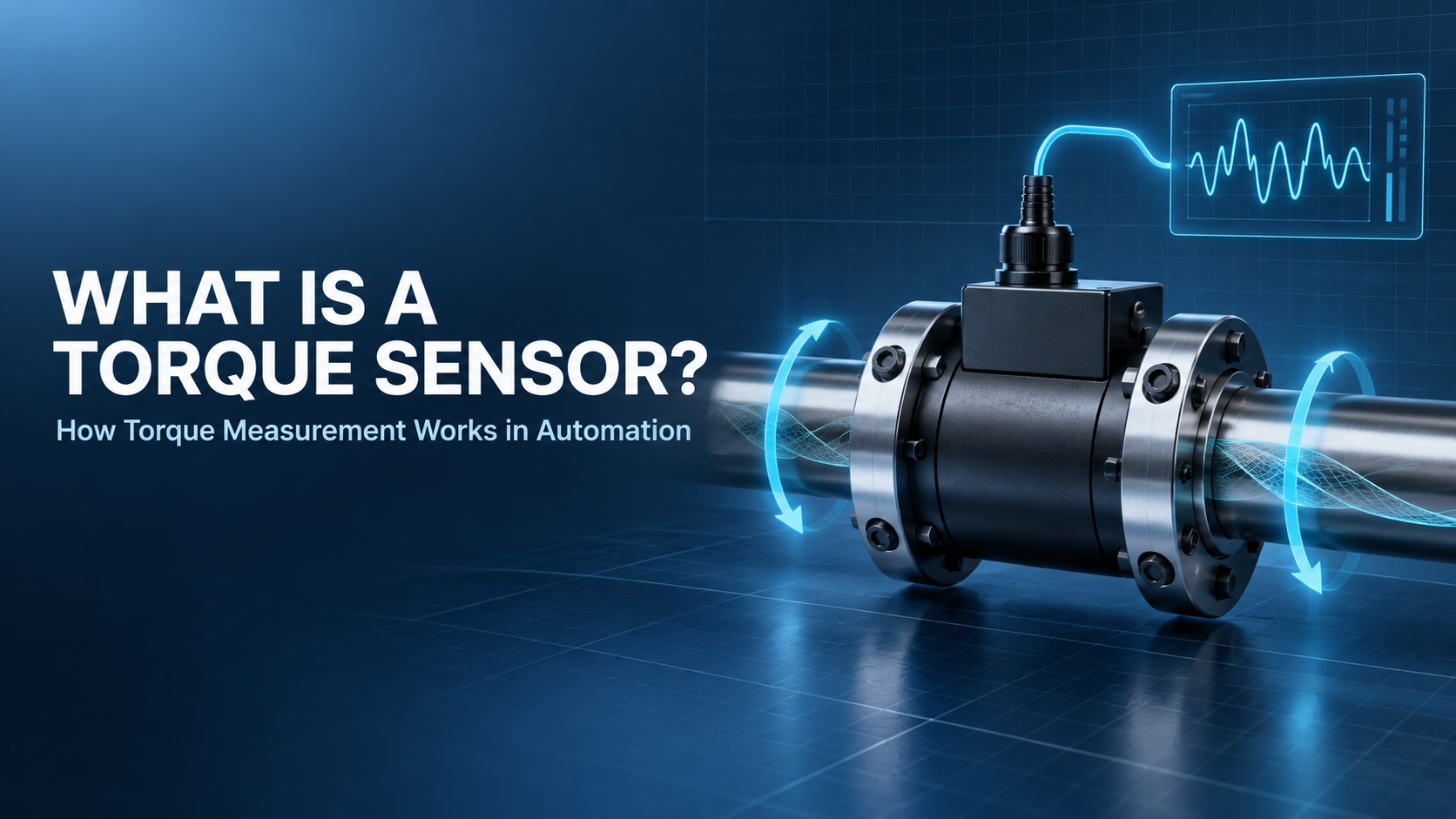
A torque sensor measures the twisting force acting on a shaft, fastener, tool, or stationary machine component. It converts that force into an electrical signal that an automation controller can display, record, or compare with programmed limits.
Torque sensors are used in automated fastening, motor and gearbox testing, robotics, winding equipment, pumps, and mixers. Their measurements help verify production processes, detect overloads, and monitor mechanical performance.
Need a replacement measurement terminal, controller, drive, or motor? Call Wake Industrial at 1-919-443-0207, email sales@wakeindustrial.com, or request an automation component quote.
What Does a Torque Sensor Measure?
Torque is the turning effect created when a force acts at a distance from an axis. For a perpendicular force:
Torque = Force × Distance
Torque is commonly expressed in newton-meters, pound-feet, or pound-inches. A sensor may measure starting torque, continuous running torque, peak torque, breakaway torque, fastening torque, or torque in both rotational directions.
The terms torque sensor and torque transducer generally describe the same type of device: a component that converts mechanical torque into a measurable electrical output.
How Does a Torque Sensor Work?
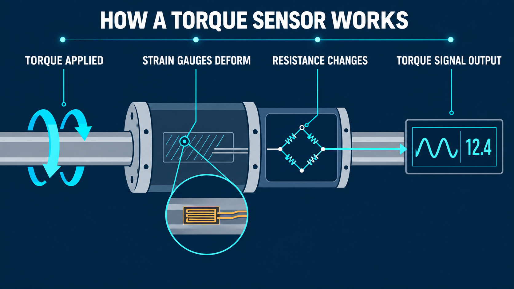
Most industrial torque sensors use strain gauges bonded to a metal measuring element. Applied torque twists the element by a very small amount. The strain gauges detect this elastic deformation through changes in electrical resistance.
The measurement process consists of five stages:
- Torque twists the measuring element.
- Strain gauges detect the resulting deformation.
- A bridge circuit converts the resistance change into a voltage.
- Measurement electronics amplify and digitize the signal.
- The controller scales the result into units such as newton-meters.
The measuring element remains within its elastic range during normal operation. When torque is removed, it returns to its original shape.
How Strain Gauges Measure Torque
Strain gauges are normally arranged in a Wheatstone bridge. As the sensing element twists, some gauges are placed in tension while others are compressed. Their resistance changes in opposite directions, increasing the bridge’s sensitivity to torque.
This arrangement also helps reduce the influence of temperature and other effects shared by the entire sensor.
An unamplified bridge sensor often specifies its sensitivity in millivolts per volt, or mV/V. For example, a 2 mV/V sensor supplied with 10 V excitation produces approximately 20 mV at rated torque:
2 mV/V × 10 V = 20 mV
Because the output is small, it requires a compatible measuring-bridge input. The Beckhoff EL3356, for example, evaluates one full resistor bridge through four- or six-wire connection technology and provides 16-bit measurement resolution.
For applications requiring several measurement channels, the Beckhoff ELM3504-0000 supports four differential full-, half-, or quarter-bridge inputs. It provides 24-bit conversion with sampling rates up to 10,000 samples per second.
How the Signal Reaches the Controller
The torque sensor is one part of a complete measurement chain.
Stage | Function |
Measuring element | Converts applied torque into elastic strain |
Strain-gauge bridge | Converts strain into a low-level voltage |
Signal conditioning | Provides excitation, amplification, filtering, or isolation |
Input electronics | Converts the signal into digital data |
Controller | Scales the reading and evaluates process limits |
HMI or database | Displays and stores the result |
Some torque sensors contain an integrated amplifier and provide a standardized output such as ±10 V, 0–10 V, 0–20 mA, or 4–20 mA. The Beckhoff EL3751 is an example of an input terminal that accepts conditioned voltage and current signals.
The input must match the sensor output. A standard voltage or current input cannot directly evaluate an unamplified mV/V bridge signal.
Rotary and Reaction Torque Sensors
Torque sensors are primarily classified by whether the measuring element rotates.
Sensor Type | How It Operates | Common Uses |
Rotary torque sensor | Rotates inline with the shaft | Motors, gearboxes, pumps, drivetrains, and rotating tools |
Reaction torque sensor | Remains stationary and measures opposing torque | Tool housings, actuators, valves, and test fixtures |
Flange torque sensor | Measures torque between rotating flanges | High-torque drivetrains and test systems |
Integrated transducer | Built into a fastening tool or spindle | Automated assembly and bolting systems |
A rotary sensor becomes part of the drivetrain. Depending on its design, power and measurement data may cross the rotating interface through slip rings, inductive coupling, frequency transmission, or wireless telemetry.
A reaction sensor measures the equal and opposite torque transferred into a stationary structure. Its measuring element does not rotate, which simplifies its electrical connection.
Static and Dynamic Torque
Static torque remains constant or changes slowly. Examples include holding a valve in position, measuring breakaway torque, or monitoring a stationary tool housing.
Dynamic torque changes during operation. It occurs when a motor accelerates, a clutch engages, a gearbox reverses direction, or a fastener reaches final torque.
Dynamic measurements require enough sensor bandwidth and sampling speed to capture rapid changes. Slow electronics may display an average value while missing short torque peaks.
How Torque Sensors Support Automation
Automated Fastening
A fastening controller can monitor final torque, peak torque, tightening angle, and cycle time. These values help determine whether a screw or bolt completed the intended tightening sequence.
Torque alone does not confirm that a joint is correct. Cross-threading, damaged threads, debris, or excessive friction can produce high torque before the required clamp load develops. Critical systems therefore evaluate torque together with angle and process timing.
Bosch Rexroth tightening systems use measurement transducers within modular tightening spindles to record torque during assembly operations. Some configurations support redundant transducers for an additional measurement channel.
Motor and Gearbox Testing
A torque transducer positioned between a motor and load can measure starting torque, continuous torque, peak torque, gearbox friction, torque ripple, and mechanical losses.
This is different from torque estimated by a servo drive. The drive calculates torque from current and motor parameters, while a physical sensor measures the mechanical torque transmitted at its position in the drivetrain.
For example, the Bosch Rexroth Indramat MST210R-0010-FT-N0CN-T302 has a rated torque of 105 Nm and a maximum torque of 240 Nm. An external torque sensor can measure how much of that output reaches the driven mechanism after mechanical losses.
When rotational speed is also known, mechanical power can be calculated:
Power (W) = 2π × Speed (rpm) × Torque (N·m) ÷ 60
Process and Condition Monitoring
Torque data can identify increasing friction, worn tooling, bearing problems, lubrication changes, blocked pumps, or mechanical obstructions. The controller can also use torque as a feedback variable to regulate winding, mixing, fastening, or testing processes.
Important Torque-Sensor Specifications
Specification | Meaning |
Rated torque | Calibrated measuring range of the sensor |
Overload capacity | Temporary load the sensor can withstand without permanent damage |
Sensitivity | Electrical output produced at rated torque |
Accuracy | Closeness of the measurement to the actual torque |
Repeatability | Consistency across repeated measurements |
Linearity | How closely output follows applied torque |
Hysteresis | Difference between increasing-load and decreasing-load readings |
Zero offset | Output present when no torque is applied |
Bandwidth | How quickly the sensor responds to changing torque |
Maximum speed | Highest permitted rotational speed for a rotary sensor |
Resolution should not be confused with accuracy. High-resolution input electronics can show very small signal changes, but total accuracy still depends on the sensor, calibration, temperature, noise, scaling, and signal conditioning.
Rated torque is also different from overload capacity. The rated value defines the intended measuring range, while overload capacity describes a higher temporary load the sensor may survive.
Why Torque Measurement Matters
Motor current and speed can indicate how a machine is operating, but they do not always show the exact mechanical torque reaching the process. A torque sensor directly measures that load.
This helps an automation system distinguish between:
- Commanded motor torque and actual transmitted torque
- A completed fastening cycle and a tool reaching its current limit
- Normal resistance and a developing obstruction
- Expected drivetrain losses and excessive mechanical friction
- A stable process and one beginning to drift
Torque data can be used for closed-loop control, overload detection, quality decisions, process documentation, and equipment condition monitoring.

Get Replacement Automation Components
A torque sensor converts twisting force into an electrical signal that a controller can evaluate. Most industrial designs use a strain-gauge bridge, although magnetoelastic, piezoelectric, optical, and other sensing technologies are also available.
The measurement electronics must match the sensor signal. Direct bridge outputs require a compatible strain-gauge input, while amplified sensors may use voltage, current, frequency, or digital communication.
Wake Industrial supplies replacement measurement terminals, controllers, servo drives, and motors used in automated torque-monitoring systems.
Call Wake Industrial at 1-919-443-0207, email sales@wakeindustrial.com, or request a quote online.
Request a Quote

Cary, NC 27513