

Mastering the Bosch Rexroth Indramat DKS: Operation and Troubleshooting Guide
21 May, 2025 | DKS, DKS Drive, DKS Servo Drive, Bosch Rexroth Indramat, DKS Troubleshooting, DKS Error Codes, DKS Fault Codes, DKS01.2-W100A-DL01-01-FW, DKS Repair, DKS Operation,
Mastering the Bosch Rexroth Indramat DKS: Operation and Troubleshooting Guide
By John Forrester
Wake Industrial is sharing information sourced from the original manufacturer's manual. Please be advised that Wake Industrial does not offer troubleshooting assistance through phone or email. For repair, replacement, or refurbishment needs, we invite you to use our quote form or call us at 1-919-443-0207. It is the user's responsibility to exercise independent judgment and caution when implementing these instructions. Wake Industrial shall not be held liable for any direct, indirect, incidental, or consequential damages to products or individuals resulting from the use of this information.
Looking for the easy to read error table? Click here.
Overview of the DKS01.2-W100A-DL01-01-FW Servo Drive
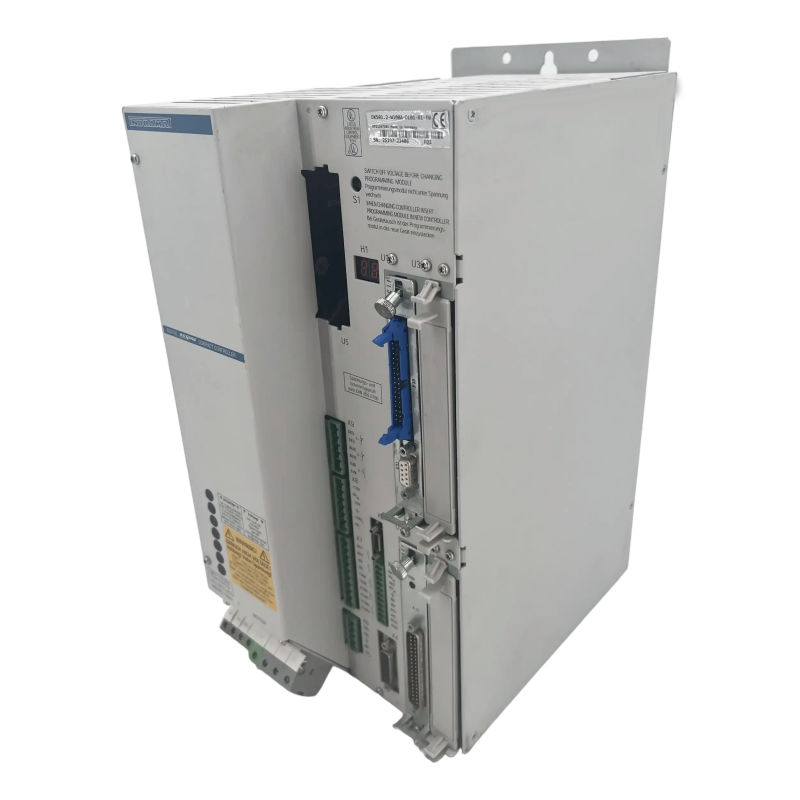
Bosch Rexroth’s Indramat DKS servo drives are integrated drive/controllers widely used in industrial automation. In this article, we provide a guide on operating and troubleshooting this drive – including the best operational practices, common failure modes, common error messages, and step-by-step troubleshooting strategies. We’ll be using a common model, the DKS01.2-W100A-DL01-01-FW as a reference throughout the article, but the operating and troubleshooting methods are applicable to all DKS servo drives. Wake Industrial wants to help keep your servo system running smoothly. Supporting legacy equipment is critical which is why Wake Industrial supplies and services all varieties of DKS Servo Drives. Call 1-919-443-0207 or fill out the quote form on this page to learn how Wake Industrial can support your DKS.
In the model code, DKS01.2 designates Series 1, Version 2 of the drive, and W100A indicates a peak current rating of 100 A. This drive accepts a three-phase 230 VAC mains input (50–60 Hz), yielding an internal DC bus around 300 V. Its power consumption can reach about 11 kVA at full load, so a robust supply is needed. The suffix DL01-01-FW on the part number tells us about the unit’s configuration: “DL” means it is equipped with a DLC single-axis positioning card, and “FW” indicates that a firmware module is included. The DLC card turns the drive into an intelligent position controller capable of executing programmed motions on its own, while the firmware provides the drive’s operating software (which must match the hardware and options for the drive to function correctly). These exact specifications will vary model to model but the operating and troubleshooting steps remain the same.
The DKS01.2-W100A-DL01-01-FW servo drive offers a continuous current of 50 A and a peak current of 100 A. It supports MDD motors and operates efficiently with a PWM frequency of 4 kHz.
Operating the DKS Servo Drive
Operation of the DKS01.2-W100A-DL01-01-FW begins with proper installation and wiring. Because this is an integrated drive, you simply need to provide the appropriate three-phase AC supply and connect the servo motor and feedback cables, without a separate external power supply module. The drive is designed for a nominal 3× 230 VAC input (approximately 208–240 V range). It’s important to verify that all three phases are present and within tolerance, as the DKS will provide a fault message if the input is missing a phase or significantly undervoltage. The drive internally rectifies the AC input to charge its DC bus, and it monitors that bus voltage closely. If the bus is too low at power-up, the drive won’t come ready; if it dips during operation an undervoltage error will be triggered.
The DKS servo drive also typically requires a stable 24 VDC auxiliary supply for its control electronics. This control power may be provided separately so that the drive’s logic and diagnostics remain on even if main AC power is off. You should apply the 24 V supply first, then bring up the main AC voltage. On power-up, the drive’s front display (H1) will show status codes. A normal startup sequence is that the display shows “bb” when the control electronics are ready and no faults are present. At this stage, however, the power stage is not yet active.
Most Indramat drives, including the DKS, incorporate a power-on inhibitor that keeps the power stage off until a command is given. In practice, you must issue a “ready to operate” or power enable signal (often a hardware input or a button) to charge the DC bus and enable the output stage. When the proper power-on signal is given, the display changes to “Ab” (armed), and once the controller enables the drive, it shows “AF” (drive enabled). At that point, the servo motor will actively hold position or follow command signals. Remember that an emergency stop or input power loss will de-energize the drive and likely produce an “Undervoltage” fault. This is normal – after resolving the condition, you can clear the fault using the S1 reset button and re-enable the drive.
Control Interfaces and Modes
The DKS01.2 drive can be configured for different control interfaces depending on the installed option cards. With the DLC positioning card (as in the -DL model), it can operate as a standalone axis controller executing programmed motion sequences. In systems without the DLC, the drive may be controlled by an external motion controller either through a ±10 V analog interface or via a SERCOS digital fiber-optic interface. These options allow the DKS to integrate into a variety of automation setups – from retrofitted analog systems to fully digital multi-axis CNC networks. Regardless of interface, the DKS provides closed-loop torque and velocity control internally, while the position loop can be handled either by the DLC card or by an external CNC/PLC. If you’re experiencing issues with your DKS interface, send in a quote via the form above or call 1-919-443-0207 to speak with a Wake Industrial representative immediately. There’s no waiting, there’s no automated messaging - you’ll speak with a real human every time.
Typical System Integration Setup
In practice, the DKS01.2-W100A-DL01-01-FW is commonly used in machinery that requires one or two servo axes. Because each DKS drive has its own rectifier and DC bus, multiple DKS units can be used independently. Each of these DKS can be simply connected to mains power and a command source. This distributed, integrated design simplifies wiring and is advantageous for retrofits or machines with separated axes. Be sure that the correct firmware module (noted by the -FW suffix) is installed in the drive and matches the hardware configuration, since an incompatible firmware or parameter set can cause a configuration fault.
One consideration in multi-axis setups is managing regenerative energy. The DKS uses an internal bleeder resistor to dissipate excess energy when a motor decelerates. Version 1.2 drives can also utilize an external capacitor bank to buffer energy during rapid decelerations. The drive will warn if the bleeder is overheating (for example, a blinking “bleeder overtemperature” warning error code 52) and will shut down with a fault (error code 20) if regenerative energy exceeds safe limits. These built-in protections help prevent damage from DC bus overvoltage conditions. In high-throughput systems with frequent fast stops, using the optional capacitor module can reduce strain on the drive and avoid overvoltage trips.
Power and Electrical Faults
Issues with the incoming power or power circuitry are a frequent cause of drive errors. If a phase is lost or the input voltage dips, the DKS will register an undervoltage fault (code 26 on the display) and shut down the output to protect itself. Conversely, if a motor decelerates too quickly and the DC bus voltage spikes beyond safe limits, the drive’s internal bleeder resistor may not absorb it all, leading to an overvoltage or a bleeder overtemp fault. The DKS also monitors output current: a sudden overcurrent trip or ground fault usually points to a short circuit in the motor windings or cables (or a failed transistor in the drive). In these events, the drive instantly disables and displays the fault code until the condition is resolved and reset.
Thermal Overload Warnings
Overheating is another common issue. The DKS tracks the temperature of its heat sink and will flash an “Amp Overtemp” warning (Code 50) if it gets too hot, allowing about 30 seconds for a controlled stop before faulting out. Likewise, an overheated motor will trigger a “Motor Overtemp” warning (Code 51) on the drive. Typical causes include a failed cooling fan, poor cabinet ventilation, or pushing the motor beyond its continuous capacity. The solution is improving cooling conditions (replacing fans, cleaning filters) or reducing the motors work load. Once temperatures return to normal, the warnings clear automatically or they can be manually reset.
Feedback and Other Errors
Problems with the servo motor’s feedback device (encoder or resolver) will also cause faults. For example, an “Absolute encoder error” (code 76) indicates the position from a multi-turn encoder doesn’t match the stored reference, often because the machine moved with power off. The fix is usually to re-home the axis and then clear the error. A general feedback fault or motor data error suggests the drive cannot read the motor’s encoder data – in that case, checking the feedback cable connections or the encoder’s health is a priority. Some internal errors (like memory or firmware faults) may likewise indicate a hardware issue that requires professional repair.
Step-by-Step Troubleshooting Strategies
When the DKS drive reports an error, a systematic approach will minimize downtime. Start with the basics: verify that all power inputs are free of physical faults and crimps. Check the three-phase AC supply (each phase should have the correct voltage) and the 24 V control power. Many faults – like an undervoltage error – can be resolved by restoring a missing phase or replacing a blown fuse. Also inspect the servo motor connections: a loose or damaged feedback cable can trigger encoder faults, and a shorted motor cable can cause overcurrent trips.
Next, read the code on the H1 display and refer to the documentation to identify the fault. The error code points you to the problem area – for example, 26 means undervoltage, while codes in the 60s denote excessive current or a short-circuit condition. Knowing this, you can focus your efforts: if it’s a supply issue, concentrate on the incoming power; if it’s a feedback error, focus on the encoder and wiring; if it’s a power electronics fault, consider the motor, cables, or the drive’s internal components.
With the likely cause in mind, isolate the problem. If you suspect the motor or cable, disconnect them (with power off) and then power up the drive alone. If the drive enables without fault when the motor is disconnected, the issue points to the motor or cable – try a different motor (if available) or test the motor windings for shorts to ground. Conversely, if the fault persists even with the motor and feedback unplugged, the drive itself may be at fault and in need of repair.
After any corrective action, reset the drive and test the system. Most faults can be cleared by pressing the S1 reset button or power-cycling the unit once the underlying issue is fixed. When you power it back on, look for the normal “bb” ready state and then “AF” (drive enabled) when you attempt to run. If the drive returns to operation without errors, you’ve successfully resolved the issue. If the error persists or returns frequently, it may indicate a deeper problem – at that point, consider consulting a Bosch Rexroth service manual or contacting a professional repair service for further diagnostics.
Listed below is a table detailing DKS Common Error Codes, their causes, and the appropriate performative action to clear these codes.
| DKS Common Error Codes | ||
|---|---|---|
| Error Code | Cause | Fix Action |
| --- Watchdog |
1. Software module not present or defective. 2. Processor defective. |
1. Install or replace the software module. 2. Replace DKS. |
| 18 "Amplifier overtemperature shutdown" |
1. Failure of the built-in blower in the equipment. 2. Failure of enclosure climate control system. 3. Wrong enclosure climate control with respect to heat removal. |
1. If a blower fails, replace the DKS. 2. Correct the functioning of the enclosure climate control system. 3. Check the size of the enclosure. |
| 19 "Motor overtemperature shutdown" |
1. The motor was overloaded. The effective torque which the motor had to produce exceeded the max. continuous stall torque for too long. 2. A break in the line to the motor temperature monitor. |
1. Check the motor layout. In the case of systems which have been operating for a relatively long time, check whether the operating conditions have changed 2. Check the wire to the motor temperature control X6/1; X6/2 for a proper ground connection or a break. |
| 20 "Bleeder overtemperature shutdown" | Continuous regenerated power too high. | Change the processing cycle. Select a DKS having a higher rated current. |
| 22 "Motor encoder error" |
1. The feedback cable is defective or not connected. 2. Motor feedback is defective. |
1. Check feedback cable. 2. If no defect is found in the cable, the feedback is defective. Replace the motor. |
| 24 "Overcurrent" | One of the three phase currents has reached a value greater than 1.5 the drive rated current. |
1. Check the motor cable. 2. Check the servo drive parameters. |
| 25 "Overvoltage" | The DC bus voltage has reached an excessively high value (Ud > 475 V). The regenerated energy of the braking motor could not be converted fast enough by the bleeder resistor. Bleeder circuit defective. | Use a DKS having a higher rated current. Check the application. Replace the DKS. |
| 26 "Undervoltage error" |
1. The DLC does not function properly in enabling the drives. 2. DKS malfunction 3. Problem in the input power (phase missing). |
1. Check the logic used to enable the drive in the DLC. 2. Eliminate the DKS malfunction (replace). 3. Eliminate the problem in the power source. |
| 33 "Error external voltage source" | Various auxiliary plug-in cards have electrically isolated inputs and outputs. An external supply voltage must be applied to properly operate these inputs and outputs. If this voltage is outside the permissible range, the above error message results. | Check external supply voltage |
| 46 "Error external encoder: maximum frequency exceeded" | The interface module used to connect the external measurement system may be operated up to a maximum input frequency. The error indicates that this maximum frequency was exceeded. | Reduce speed. |
| 47 "Error detecting reference mark on external encoder" |
1. DLF 1.1 defective. 2. Reference mark channel on the external encoder defective. |
1. Replace the DLF 1.1 card. 2. Service the Drive |
| 48 "Absolute Encoder Battery Voltage Low" | Battery voltage too low | Replace the battery as soon as possible. |
| 50 "Amplifier overtemperature warning" (blinking) |
1. Failure of blower in the unit 2. Failure of the enclosure climate control system 3. Inadequate cooling in the enclosure. |
1. In the event of a blower failure, replace the DKS. 2. Repair the enclosure climate control system 3. Check the size of the enclosure. |
| 51 "Motor overtemperature warning" (blinking) | The motor was overloaded. The effective torque required of the motor exceeded the maximum permissible continuous stall torque for too long. | Check the motor layout. In the case of systems which have been operating for a relatively long time, check whether the operating conditions have changed |
| 52 "Bleeder overtemperature warning" (blinking) | The motor briefly enters the bleeder‘s overload range when it reverses | Change the processing cycle. Select a DKS having a higher rated current. |
| 60 "Bridge circuit overcurrent" |
1. Short circuit in the motor cable 2. Power output section of the DKS is defective. |
1. Check the motor cable for a short circuit. If there is a short, replace cable. 2. Replace DKS. |
| 61 "Ground fault (earth conn) circuit tripped" |
1. Defective motor cable 2. Short to ground in the motor. |
1.Check the motor cable and motor for a short to ground and if necessary replace. |
| 67 "Hardware synchronization defective" | The pulse width modulator on the DKS is synchronized by the phase control circuit. Proper synchronization is monitored. If synchronization is incorrect, this error message is output. | 1. Replace DKS; send in for inspection. |
| 68 "Brake Fault" |
1. The supply voltage for the brake is produced in the DKS. It is monitored (24 V ±10%). The brake is not properly connected; short circuit. 2. The motor cable is loose or is incorrectly connected (wrong polarity). 3. Brake defective. 4. DKS defective. |
1. Check the supply voltage. 2. Check the motor cable. 3. Replace the motor. 4. Replace the DKS. |
| 69 "±15 Voltage error" | External short circuit, DKS defective. | Replace DKS, correct the short circuit. |
| 70 "+24 Voltage error" | External short circuit, DKS defective. | Replace DKS, correct the short circuit. |
| 71 "+10 Volt error" | Defect in DKS | Replace DKS |
| 72 "+8 Volt error" | Short circuit in the motor encoder cable or in the cable for external encoders. | Check cable and replace if necessary. |
| 76 "Absolute encoder error" |
1. It is the first time the unit was powered on (stored position is not valid). 2. The axis was moved in the power-off condition by more than the distance parameterized in absolute value encoder monitoring window P-0-0097 and is outside its position window. 3. Position initialization is incorrect (feedback defective). |
1. Clear the error (establish axis reference). 2. Check whether a new traverse command will cause damage. If not, clear the error. 3. Check the reference position. If the reference dimension is incorrect, replace the motor. |
If you're still encountering issues after following these troubleshooting steps, then it may be time to contact Wake Industrial for a Drive replacment or repair.
Conclusion
In summary, the DKS are a robust and versatile servo drive series. By understanding its operation and diagnostic codes, you can address most issues that arise and minimize downtime. If a drive repeatedly faults due to internal problems or reaches the end of its service life, a replacement or professional repair may be necessary.
If you need to purchase a replacement DKS drive or have one repaired, consider Wake Industrial. Wake Industrial stocks refurbished Bosch Rexroth Indramat drives and offers reliable repair services to get your equipment back online quickly. Please note that while Wake Industrial does not provide formal technical support, they have a convenient website chat tool that can assist with common troubleshooting tips and guide you to the right product. Simply click on the Chat with a Rep Now bubble to begin using the tool. Reach out to Wake Industrial by calling 1-919-443-0207 for quality servo drive products and expert repair solutions.
Wake Industrial is sharing information sourced from the original manufacturer's manual. Please be advised that Wake Industrial does not offer troubleshooting assistance through phone or email. For repair, replacement, or refurbishment needs, we invite you to use our quote form or call us at 1-919-443-0207. It is the user's responsibility to exercise independent judgment and caution when implementing these instructions. Wake Industrial shall not be held liable for any direct, indirect, incidental, or consequential damages to products or individuals resulting from the use of this information.
Request a Quote
Cary, NC 27513


