


SC402-003-T3 Pacific Scientific
Wake Industrial LLC is not an authorized distributor of this product.
Wake Industrial LLC is not an authorized distributor of this product.
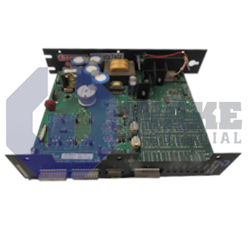
The Pacific Scientific SC402-003-T3 is a servo drive from the SC400 Servo Drives series. It provides a continuous output current of 3.50 Amps and a peak output current of 7.0 Amps. The main input fuse is rated for 20 Amps at 250 Volts, and the control supply fuse is 0.5 Amps at 250 Volts.
Internal Product Review
The SC402-003-T3 is a Pacific Scientific SC400 servo drive with 3.50 A continuous output current and 7.0 A peak output current. A 2.0 V/Krpm tach gradient and 0.63 V/A current monitor scale support clean tuning and dependable feedback in motion-control applications. A well-balanced drive for precise servo performance.
 Have a part to sell?
 Wake Industrial Warranty
To contact sales for pricing and lead time:
Payment Methods


Shipping Methods


Our Credentials


Product Description:
The SC402-003-T3 servo drive is produced by Pacific Scientific as part of the SC400 Servo Drives series. Designed for closed-loop velocity and torque regulation of brushless motors, it converts three-phase mains power into controlled current that can be commanded by a motion controller in automated assembly, packaging, and material-handling cells. By housing power electronics, signal conditioning, and protective circuits in one module, the unit simplifies panel layout and provides the electrical interface between the plant supply and the servo actuator. Its integrated layout keeps drive and interface functions in a single cabinet-mounted unit.
During operation, the drive can deliver a continuous phase current of 3.50 A, while short acceleration demands are met by a peak capability of 7.0 A. An input supply excursion to 253 VAC causes an AC-input overvoltage fault that halts output to protect the inverter. Mains conductors are protected by a 20 A, 250 V fuse, and the separate user supply provides 10 mA from the positive auxiliary rail for low-power external circuitry. The logic section is isolated by a 0.5 A, 250 V control-supply fuse, which separates low-level electronics from the main power path. This arrangement supports stable power handling during normal running and brief demand spikes without mixing user-side signals with the main output stage.
The negative auxiliary rail supplies -12 VDC for analog interface devices that require bipolar signaling. Command scaling reaches full output at 4.2 V, and the built-in current monitor follows a 0.63 V/A conversion factor for signal observation. Tachometer feedback is available at up to 2.0 V/Krpm, and the monitor output reaches 4.4 VDC with a 1 kΩ source impedance, so connected equipment should present at least 20 kΩ of load. Fault reporting uses an open-collector sink rated at 25 mA and 30 VDC, giving the control system a discrete alarm signal when protection circuits trip. These interface values support clear signal transfer to external command sources, panel meters, and controller inputs that rely on analog scaling.









