


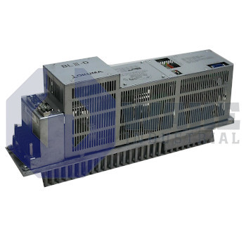
BLIII-D Okuma
Wake Industrial LLC is not an authorized distributor of this product.
Wake Industrial LLC is not an authorized distributor of this product.
The Okuma BLIII-D is part of the BL Servo Drives series and supports capacity settings of 15, 30, 50, 75, and 150 Amps. It operates within an input voltage range of 170 to 242 V AC and a line frequency of 50 or 60 Hz. This model provides input terminals R, S, T, and features alarm LEDs for OCM, OCS, OV, UV, LOSS, FOH, and CPU.
Internal Product Review
The BLIII-D is an Okuma BL servo drive with 50/60 Hz line compatibility and a 170 to 242 V AC input range. Diagnostic coverage is strong, with alarm LEDs for OCM through CPU and capacity settings from 15A to 150A, making the unit a dependable choice for servo system integration.
 Have a part to sell?
 Wake Industrial Warranty
To contact sales for pricing and lead time:
Payment Methods


Shipping Methods


Our Credentials


Product Description:
The BLIII-D is a servo drive module manufactured by Okuma as part of the BL Servo Drives series. Designed for closed-loop motion systems, it converts a plant’s three-phase mains supply into controlled current for BL synchronous motors. By delivering programmable power, the unit supports precise positioning, rapid acceleration, and real-time fault response in CNC machining centers, automated lathes, and other equipment that requires continuous axis feedback. Its onboard switches and connectors allow the drive to be matched to different axis requirements for capacity selection, braking, and monitoring functions.
Seven alarm indicators, identified as OCM, OCS, OV, UV, LOSS, FOH, CPU, show fault conditions such as overcurrent, overvoltage, undervoltage, loss detection, overheating, and processor errors. Output capacity can be selected in five rated steps of 15A, 30A, 50A, 75A, 150A, so one drive can support several motor sizes. Mains power enters through R, S, T, and the control logic accepts a utility frequency of 50/60 Hz. The input section tolerates up to 242 V AC, which gives additional margin during high-line conditions. Switches SW1 through SW6, together with the CN20 capacity disc or connector, adjust fault thresholds, brake use, and feedback scaling, while SW7 and SW8 are not used.
Undervoltage protection activates when the supply falls to 170 V AC, allowing the drive to remain in normal operation during brief voltage dips above that level. Regenerative energy is routed to an external resistor through CN20 (XB-DBR), which provides a direct connection point for braking hardware. The status LED chart DC=Orange;PON=Green;OP=Orange;OCM-CPU=Red separates power and operating states from alarm conditions in a clear format. Output tuning follows the SW1 map 15A=OFF;30A=4;50A=3;75A=3,4;150A=2, allowing the current range to be changed for the connected motor. Clear terminal and switch labeling keeps the selected operating range aligned with the installed axis hardware.









