


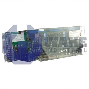
BLII-D200A Okuma
Wake Industrial LLC is not an authorized distributor of this product.
Wake Industrial LLC is not an authorized distributor of this product.
The Okuma BLII-D200A belongs to the BL Servo Drives series and provides control for a single axis using a SVC II board. It features a power unit capacity of 200 Amps and a control circuit source of 5 Volts. The drive is equipped with a control protection fuse rated at 3.2 Amps and a motor overcurrent alarm that activates at 150 percent of the limit.
Internal Product Review
The BLII-D200A is an Okuma BL servo drive with a 200 A power unit capacity. A 5 V control circuit source and SVC II board support stable command processing and dependable integration in machine servo systems. Single-axis architecture keeps configuration straightforward, and the 150% motor overcurrent alarm limit is a strong safeguard for demanding motion control.
 Have a part to sell?
 Wake Industrial Warranty
To contact sales for pricing and lead time:
Payment Methods


Shipping Methods


Our Credentials


Product Description:
The BLII-D200A is a single-axis servo drive from Okuma’s BL Servo Drives series intended for closed-loop motion control in machining centers and automated handling lines. By regulating current into a matched BL servo motor, it converts numerical commands from the CNC into precise torque and speed, supplying the feedback bandwidth needed for industrial positioning tasks. Its closed-loop architecture supports stable speed regulation and repeatable positioning when load conditions change during machine operation.
This unit governs one mechanical axis, with an axis count of 1, and its internal power stage is sized for 200 A of peak output to cover rapid acceleration profiles. Logic electronics are energized from a dedicated 5 V control circuit, which helps isolate signal integrity from the high-power bus. To protect the motor phase wiring, an overcurrent alarm trips when load demand reaches 150% of limit, prompting immediate deceleration. Velocity feedback is presented to external diagnostics as a scaled analog of ±10 V/±3750 rpm, allowing a drive monitor to correlate voltage with shaft speed during tuning. Command processing is handled by the SVC II board, which executes current-loop and velocity-loop algorithms while exchanging reference data through the designated connectors.
The control circuit is safeguarded by a 3.2 A fuse that disconnects low-voltage power under fault conditions, and field wiring terminates on M4 terminal screws suited to common ring lugs. The reference trajectory arrives through a 20-cavity current-command connector, while the load output and motor brake lines use separate two- and five-cavity housings that keep high current apart from release signals. For real-time load verification, the drive outputs a torque indicator of 10 V/(Torque Limit), allowing external controllers to gauge mechanical stress without a dedicated sensor. Separate connector groups also help organize control, brake, and power wiring inside the cabinet.









