


SERVOSTAR-446M-C Kollmorgen
Wake Industrial LLC is not an authorized distributor of this product.
No Tariffs On US Orders- Straightforward Pricing: No Rush Fees, No Credit Card Fees
Current response time:
3 Minutes
18 Seconds
The SERVOSTAR-446M-C is a servo drive from the S400 Servo Drives series by Kollmorgen. It delivers a rated output current of 6 Arms and a peak output current of 12 Arms, and supports a maximum installed load of 12 kVA. The drive has 4 digital inputs, 2 digital outputs, and an auxiliary voltage of 24 VDC.


To contact sales for pricing and lead time:
Payment Methods


Shipping Methods


Our Credentials


Product Description:
The SERVOSTAR-446M-C servo drive is produced by Kollmorgen and belongs to the S400 Servo Drives series. Designed for closed-loop motion systems, the unit converts DC link energy into controlled three-phase output so that a synchronous or induction motor can follow precise torque, speed, or position commands in automated machinery. It serves as the power interface between a motion controller and the motor, enabling material handling, packaging, or assembly tasks that require repeatable dynamics.
During continuous operation, the drive supplies a rated phase current of 6 Arms, while transient loads can be covered with a peak capacity of 12 Arms. The internal power bridge is coordinated by an output stage clock of 8 kHz, and this switching frequency supports smooth current regulation while helping keep audible noise low. Up to 12 kVA of apparent power can be supported on the DC bus, so the drive can energize medium-frame servo motors in coordinated axes. Protection against line surges is provided by an overvoltage threshold set at 750 V, and the control board accepts four digital inputs and two digital outputs for enable, fault reset, or mode selection tasks. With quiescent dissipation limited to 15 W, standby heat load on the enclosure remains minimal.
Control electronics are fed from an auxiliary supply of 24 VDC, allowing the logic to stay active during main power removal for bus communication and safe shutdown sequences. The power stage is tolerant of machine cabling that presents inductances from 7.5 mH to 40 mH, a range suited to most low-inertia servomotors and cable lengths typical of cabinet-mounted drives. Under rated load, the device dissipates 60 W, and that heat must be removed by panel ventilation to keep component temperatures within limits. Mechanical integration is simplified by a width of 100 mm, a depth of 240 mm, and a height of 267 mm, while a weight of only 3 kg permits high-density stacking on DIN rail or backplate assemblies.
24 VDC
240 mm
4
2
267 mm
12 kVA
Frequently Asked Questions about SERVOSTAR-446M-C:
Q: What is the rated output current of the SERVOSTAR-446M-C servo drive?
A: The SERVOSTAR-446M-C delivers a rated output current of 6 Arms for continuous operation.
Q: What is the maximum installed load capacity for the SERVOSTAR-446M-C?
A: This servo drive can support a maximum installed load of 12 kVA.
Q: How many digital inputs are provided on the SERVOSTAR-446M-C servo drive?
A: There are four digital inputs available on the SERVOSTAR-446M-C.
Q: What auxiliary voltage does the SERVOSTAR-446M-C require?
A: The auxiliary voltage required for the SERVOSTAR-446M-C is 24 VDC.
Q: What is the overvoltage threshold of the SERVOSTAR-446M-C?
A: The overvoltage protection on this model is set at a threshold of 750 V.
Instructions
How to Determine What Torque You Need for Your Servo Motors
When building a robotic system with servo motors, determining the appropriate torque for each motor is essential. Torque is what allows the servo motor to effectively lift, hold, or move an object. Without sufficient torque, your motor either won’t perform as expected or may damage itself trying.
Here, we’ll break down how to calculate the torque you need, then pivot into some key nuances around how torque works in different contexts.
What Is Torque?
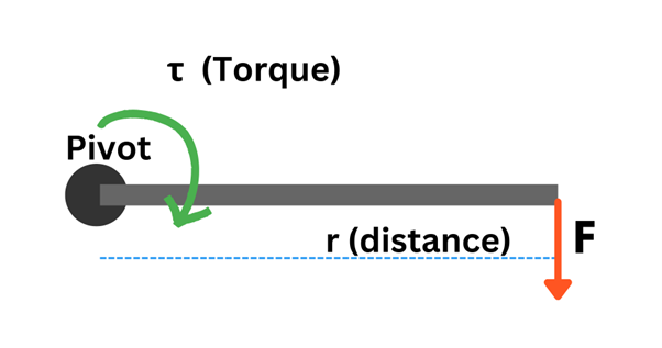
Torque is a force applied over a distance that causes rotation. You use torque every day when you twist open a jar or turn a doorknob. In the case of servo motors—specifically in robotics—torque determines how much weight a motor can rotate at a certain distance away from its axis. Think about a robotic arm lifting a heavy object: the motor's torque directly affects how much weight the arm can lift, and at what speed.
Mathematically, torque is expressed as:
τ = r × F
- τ is torque,
- r is the distance from the axis of rotation,
- F is the force applied.
If that feels abstract, consider that F is usually the force caused by gravity, meaning it depends on the weight of the object and its distance from the motor's center.
Torque and Servo Motors: The Core Relationship
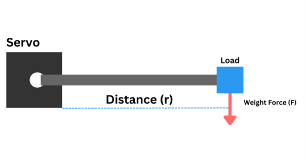
Servo motors are frequently used in robotic arms or other machines with rotational mechanisms. The amount of torque a servo motor can exert determines its capability to perform mechanical tasks, especially when dealing with varying loads.
The lever arm length—the distance from the rotation point to the load—amplifies the effect of the weight being moved. A longer lever arm requires more torque even if the weight remains the same. So, as we dive into calculations, remember that torque isn't just about force; it’s also about how far away from the motor's axis that force is applied.
Formula Recap
The standard torque equation for servo motors typically used in applications like robotic arms can be expanded slightly:
τ = r × m × g
- r is the distance from the motor's axis to where the load is applied,
- m is the mass of the item being moved (in kilograms),
- g is the acceleration of gravity (~9.81 m/s²).
Let’s translate this into something more immediately practical: a robotic arm needs torque to lift an object at the end of the arm. If the arm is long, you’ll need more torque to achieve that same lift, even if the object you’re lifting doesn’t change in weight.
Components of Torque in Servo Motors
1. Weight of Components
The force caused by the weight of objects being moved is simple physics. Every load you expect the motor to handle has a weight. Multiplied by gravity, that’s your F.
A robotic arm lifting a box must overcome the weight of the box. However, the motor also needs to account for the weight of the components themselves, like robotic arm links or grippers.
2. Distance from the Pivot
The lever arm length is just as crucial. Calculating torque by only considering force and weight without factoring in the arm’s length will result in inaccurate torque requirements and potentially a poor design.
Case Study: A Simple Robotic Arm
Imagine an arm that needs to lift a 1.5 kg box at the end of a 0.5-meter-long arm.
- m = 1.5 kg
- r = 0.5 m
- g = 9.81 m/s² (constant)
We’re now ready to plug in values:
τ = r × m × g
τ = 0.5 m × 1.5 kg × 9.81 m/s²
τ = 7.36 Nm
This means you require a minimum torque of 7.36 Newton-meters (Nm) to lift the box at the end of this particular robotic arm.
Angular Acceleration
In any instance where you need the servo motor to move a load and not just hold it, you must also account for angular acceleration. Angular acceleration means your motor needs extra torque at the beginning and during changes in movement. To calculate it:
τ = I × α
- I is the moment of inertia of the robot arm (resistance to angular motion),
- α is angular acceleration.
This means that for movements such as high-speed rotations or rapid direction changes, torque requirements jump. The speed with which the load moves and how quickly the direction changes are factored into torque calculations for dynamic motion.
Final Thoughts
To summarize everything, calculating torque isn’t just as simple as deciding how heavy a load is. It requires you to think about:
- Distance (where the weight is applied from the axis),
- Weight of the object being moved,
- The weight of other mechanical components (like links and joints inside the machine),
- Angular acceleration, especially if the motor will be moving or changing directions rapidly,
- Safety margins (plan a buffer of 20-30% torque capability beyond the minimum).
The general idea is that the larger the load or the further away from the pivot, the more torque you need. By thinking through all of these details, you can properly size your servo motor torque needs, ensuring your motor will handle everything smoothly without underperformance during operation.
Get expert servo motor guidance and competitive pricing from Wake Industrial. Whether you need one motor or a complete system, we'll help you find the right solution at the right price. Call 1-919-443-0207 now for a quick quote or email sales@wakeindustrial.com to browse our extensive servo motor inventory.
Instructions
How to Determine What Torque You Need for Your Servo Motors
When building a robotic system with servo motors, determining the appropriate torque for each motor is essential. Torque is what allows the servo motor to effectively lift, hold, or move an object. Without sufficient torque, your motor either won’t perform as expected or may damage itself trying.
Here, we’ll break down how to calculate the torque you need, then pivot into some key nuances around how torque works in different contexts.
What Is Torque?
Torque is a force applied over a distance that causes rotation. You use torque every day when you twist open a jar or turn a doorknob. In the case of servo motors—specifically in robotics—torque determines how much weight a motor can rotate at a certain distance away from its axis. Think about a robotic arm lifting a heavy object: the motor's torque directly affects how much weight the arm can lift, and at what speed.
Mathematically, torque is expressed as:
τ = r × F
- τ is torque,
- r is the distance from the axis of rotation,
- F is the force applied.
If that feels abstract, consider that F is usually the force caused by gravity, meaning it depends on the weight of the object and its distance from the motor's center.
Torque and Servo Motors: The Core Relationship
Servo motors are frequently used in robotic arms or other machines with rotational mechanisms. The amount of torque a servo motor can exert determines its capability to perform mechanical tasks, especially when dealing with varying loads.
The lever arm length—the distance from the rotation point to the load—amplifies the effect of the weight being moved. A longer lever arm requires more torque even if the weight remains the same. So, as we dive into calculations, remember that torque isn't just about force; it’s also about how far away from the motor's axis that force is applied.
Formula Recap
The standard torque equation for servo motors typically used in applications like robotic arms can be expanded slightly:
τ = r × m × g
- r is the distance from the motor's axis to where the load is applied,
- m is the mass of the item being moved (in kilograms),
- g is the acceleration of gravity (~9.81 m/s²).
Let’s translate this into something more immediately practical: a robotic arm needs torque to lift an object at the end of the arm. If the arm is long, you’ll need more torque to achieve that same lift, even if the object you’re lifting doesn’t change in weight.
Components of Torque in Servo Motors
1. Weight of Components
The force caused by the weight of objects being moved is simple physics. Every load you expect the motor to handle has a weight. Multiplied by gravity, that’s your F.
A robotic arm lifting a box must overcome the weight of the box. However, the motor also needs to account for the weight of the components themselves, like robotic arm links or grippers.
2. Distance from the Pivot
The lever arm length is just as crucial. Calculating torque by only considering force and weight without factoring in the arm’s length will result in inaccurate torque requirements and potentially a poor design.
Case Study: A Simple Robotic Arm
Imagine an arm that needs to lift a 1.5 kg box at the end of a 0.5-meter-long arm.
- m = 1.5 kg
- r = 0.5 m
- g = 9.81 m/s² (constant)
We’re now ready to plug in values:
τ = r × m × g
τ = 0.5 m × 1.5 kg × 9.81 m/s²
τ = 7.36 Nm
This means you require a minimum torque of 7.36 Newton-meters (Nm) to lift the box at the end of this particular robotic arm.
Angular Acceleration
In any instance where you need the servo motor to move a load and not just hold it, you must also account for angular acceleration. Angular acceleration means your motor needs extra torque at the beginning and during changes in movement. To calculate it:
τ = I × α
- I is the moment of inertia of the robot arm (resistance to angular motion),
- α is angular acceleration.
This means that for movements such as high-speed rotations or rapid direction changes, torque requirements jump. The speed with which the load moves and how quickly the direction changes are factored into torque calculations for dynamic motion.
Final Thoughts
To summarize everything, calculating torque isn’t just as simple as deciding how heavy a load is. It requires you to think about:
- Distance (where the weight is applied from the axis),
- Weight of the object being moved,
- The weight of other mechanical components (like links and joints inside the machine),
- Angular acceleration, especially if the motor will be moving or changing directions rapidly,
- Safety margins (plan a buffer of 20-30% torque capability beyond the minimum).
The general idea is that the larger the load or the further away from the pivot, the more torque you need. By thinking through all of these details, you can properly size your servo motor torque needs, ensuring your motor will handle everything smoothly without underperformance during operation.
Get expert servo motor guidance and competitive pricing from Wake Industrial. Whether you need one motor or a complete system, we'll help you find the right solution at the right price. Call 1-919-443-0207 now for a quick quote or email sales@wakeindustrial.com to browse our extensive servo motor inventory.









