


VT-VRPA1-527-11/V0/PV-RTP Bosch Rexroth Indramat
Wake Industrial LLC is not an authorized distributor of this product.
- Straightforward Pricing: No Rush Fees, No Credit Card Fees
The Bosch Rexroth Indramat VT-VRPA1-527-11/V0/PV-RTP is part of the VT-VRPA Electric Amplifiers series and features a nominal supply voltage of 24 V DC with maximum power consumption of 35 watts. It is equipped with a DIN 41612-F32 connector and supports a maximum solenoid current of 2.7 amps and solenoid power of 25 watts. The amplifier offers adjustable ramp times from 0.05 to 5 seconds and uses a command potentiometer with a resistance of 1 kiloohm.


To contact sales for pricing and lead time:
Payment Methods


Shipping Methods


Our Credentials


Product Description:
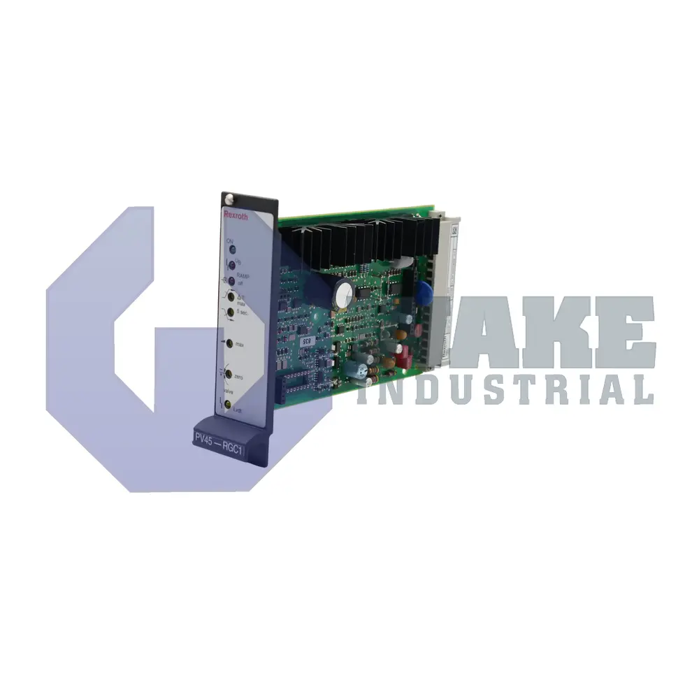
The VT-VRPA1-527-11/V0/PV-RTP is an electric amplifier module produced by Bosch Rexroth Indramat for the VT-VRPA Electric Amplifiers series. Designed for rack installation, the card shapes command and feedback signals so a proportional hydraulic valve receives controlled coil current. By inserting adjustable ramps and limit checks, it allows a PLC or process controller to drive motion profiles electrically, replacing mechanical throttles in industrial presses, test rigs, and handling equipment.
Primary power is supplied by a nominal 24 V DC rail, and at full load the board draws up to 1.5 A, simplifying cabinet power supply sizing. Internal circuitry dissipates no more than 35 W, so natural convection keeps temperatures within design margins. A front-panel trimmer selects a ramp from 0.05 s to 5 s; these time constants let the application soften spool acceleration or achieve near-step responses. The enable channel accepts at least 8.5 V DC before the output stages activate, preventing inadvertent startups during low-voltage conditions. For manual reference generation, the module offers a 10 V DC, 10 mA potentiometer supply suited to a 1 kΩ command potentiometer, giving consistent scaling across installations.
Once enabled, the power section can deliver up to 2.7 A or 25 W to the proportional solenoid, matching common NG6 and NG10 valve coils. A fault monitor supplies 100 mA to the error line if current faults or cable breaks are detected, while a ramp-off input greater than 8.5 V DC forces the output to zero regardless of the active ramp. Feedback transducers may be wired up to 50 m from the cabinet without degrading regulation accuracy. Zero adjustment of ±10% compensates for coil tolerances after installation. All terminations route through a DIN 41612-F32 connector, and shielding on the backplane keeps high-current solenoid lines separate from analog reference tracks.









