


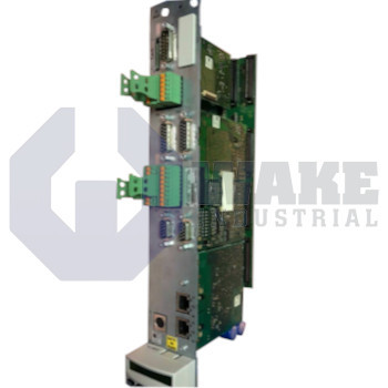
CDB01.1C-S3-ENS-ENS-NNN-MA1-L1-S-NN-FW Bosch Rexroth Indramat
Wake Industrial LLC is not an authorized distributor of this product.
MPN: R911323815
No Tariffs On US Orders- Straightforward Pricing: No Rush Fees, No Credit Card Fees
Current response time:
3 Minutes
57 Seconds
The Bosch Rexroth Indramat CDB01.1C-S3-ENS-ENS-NNN-MA1-L1-S-NN-FW is part of the CDB Control Units series and features SERCOS III control communication and dual ENS encoder interfaces with 12-bit width. This unit includes analog inputs and outputs of ±10 V each, 12-bit I/O resolution, and multiple D-Sub connectors for interfacing. It also provides a starting lockout safety function with a 24 V, 1 A safety acknowledgment supply and supports EN60204-1 Category 0 safety stop.


To contact sales for pricing and lead time:
Payment Methods


Shipping Methods


Our Credentials


Product Description:
The CDB01.1C-S3-ENS-ENS-NNN-MA1-L1-S-NN-FW is a compact control section from Bosch Rexroth Indramat that belongs to the CDB Control Units series. The board mounts on the front of an IndraDrive power module and provides the local intelligence that links motion hardware to higher-level controllers. Installed in modular drive cabinets, it executes signal processing, fieldbus exchange, and safety supervision for connected power sections. By managing network communication, encoder feedback, and analog reference channels, the unit closes velocity and position loops in automation cells that include packaging machinery, palletizers, and metal-cutting stations. Its front-mounted layout also keeps control interfaces accessible at the drive face for organized cabinet wiring.
Primary fieldbus communication is handled through SERCOS III, which is accessed through an 8-pin RJ-45 port and supports deterministic cycle times for tightly synchronized multi-axis control. Feedback reaches the CPU through 2 x ENS encoder channels. Each channel digitizes position data with 12-bit resolution, is powered from an internal rail of 11.6 V, and accepts differential TTL edges up to 400 kHz. The two encoder channels share a 15-pin female D-Sub connector, which reduces panel space and cable count while preserving phase fidelity during rapid moves. This arrangement also supports applications that need more than one feedback source on the same axis.
The MA1 option provides 2 x ±10 V analog inputs plus two mirrored ±10 V outputs. Both directions use 12-bit resolution through a 15-pin female D-Sub connector, allowing external PLC setpoints or process monitors to interact with the drive during operation. Safety wiring terminates on a 9-pin female D-Sub connector and is energized by a 24 V / 1 A acknowledgment supply. A 24 V, 3 mA control line supervises the Starting Lockout function so the drive cannot enable until the circuit is confirmed. When a fault is detected, the integrated stop follows EN60204-1 Cat 0, removing power to the motor in the shortest possible time.









