


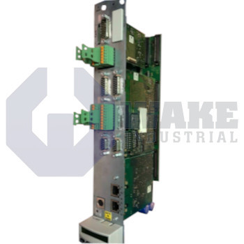
CDB01.1C-S3-EN2-EN2-NNN-NNN-L1-S-NN-FW Bosch Rexroth Indramat
Wake Industrial LLC is not an authorized distributor of this product.
MPN: R911318143
No Tariffs On US Orders- Straightforward Pricing: No Rush Fees, No Credit Card Fees
Current response time:
4 Minutes
37 Seconds
The Bosch Rexroth Indramat CDB01.1C-S3-EN2-EN2-NNN-NNN-L1-S-NN-FW is part of the CDB Control Units series. It features a SERCOS III communication interface and supports encoder inputs such as EnDat 2.1, 1 Vpp, and 5 V TTL. This unit has analog outputs rated at 1 mA current and 5 V voltage, with a maximum I/O supply current of 1.1 A.


To contact sales for pricing and lead time:
Payment Methods


Shipping Methods


Our Credentials


Product Description:
The CDB01.1C-S3-EN2-EN2-NNN-NNN-L1-S-NN-FW is a control section manufactured by Bosch Rexroth Indramat for the CDB Control Units series. Installed in a Rexroth drive stack, this card provides the processing resources that coordinate axis commands, fieldbus traffic, and encoder feedback so the power stage can regulate motor torque and speed. It is chosen for multi-axis machinery where fast cycle updates and distributed diagnostics are required in industrial automation cells.
A built-in communication slot accepts the SERCOS III protocol, enabling deterministic real-time exchange with higher-level PLCs. Two analog monitor channels source 5 V and sink up to 1 mA, giving the drive a low-burden path for speed or torque references. The encoder interface recognizes EnDat 2.1, ±1 Vpp, and 5 V TTL signals to match a broad range of feedback transducers. Each digital output may dissipate 400 mJ of inductive energy, so external relays must include proper flyback suppression. The S3 communication daughterboard draws 1 W, the dual EN2 I/O modules require 6 W, the L1 local bus module consumes 2 W, and the standard front panel adds another watt, so the total internal load stays within the cabinet thermal plan. Individual outputs deliver 500 mA for actuators, and inductive loads are time-stamped by a 4 µs probe pulse, assisting motion capture functions.
The backplane can supply up to 1.1 A of 24 V logic current, leaving headroom for additional sensor power. A 4 µs probe pulse aligns encoder position with external triggers. Functional safety wiring lands on a D-Sub female, 9-pin connector, while the drive-enable circuit expects a DC 24 V / 1 A acknowledgment and monitors a separate 24 V, 3 mA start-inhibit input. Network cabling uses the RJ-45, 8-pin Sercos connector, and standby demand remains modest because the installed modules have limited power draw.









