


E4809-045-145-A Okuma
Wake Industrial LLC is not an authorized distributor of this product.
MPN: 1911-1224-8-99
No Tariffs On US Orders- Straightforward Pricing: No Rush Fees, No Credit Card Fees
Current response time:
3 Minutes
0 Seconds
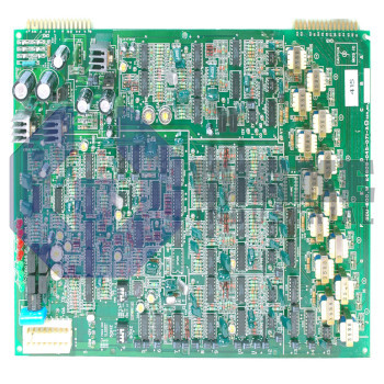
The Okuma E4809-045-145-A is a spindle drive top board in the E4809 CNC Boards series. It features connectors CN5 to CN7, operates with a supply voltage of 300 V DC at CN7, and has two seven-segment displays. The board is compatible with VAC3-D11 and VAC3-D22 drives and includes an optical fiber interface as well as feedback via optical pulses.


To contact sales for pricing and lead time:
Payment Methods


Shipping Methods


Our Credentials


Product Description:
The E4809-045-145-A is a spindle-drive top board developed by Okuma for the E4809 CNC Boards series. Installed at the upper level of a VAC3 spindle amplifier stack, the board routes command, feedback, and status data between the drive and the machine controller to keep spindle speed and orientation within specified tolerances. By hosting dedicated connectors, LEDs, and conversion circuitry, it forms the electrical interface layer that ties optical feedback devices, resolver signals, and power-stage logic together inside computer numerical control machining centers.
Main signal traffic enters through the board interface set marked CN5 to CN7, while the CN7 edge also receives a spindle-bus supply of 300 V DC. Firmware and component ratings match the VAC3 platform, so only the VAC3-D11 and VAC3-D22 drive types are supported. Shaft position data arriving as resolver sine and cosine waves is translated into Optical Pulses that downstream logic can count at high frequency. For external encoder emulation, the dedicated pulse generator outlet at CN2 forwards those pulses to an SPC6 card that closes the speed loop. A fiber-optic interface is present for noise-immune transport of supervisory commands, and the resolver connector CN3 accepts four-wire shielded cabling. Two seven-segment displays show code numbers that help with status checks and error localization.
Visual diagnostics are expanded by three operation LEDs and a larger bank of 13 status LEDs, with individual points labeled M1, M2, M3 for quick recognition of basic run states. Hardware behavior can be altered through six DIP switches that are factory set to SW1 to SW6 OFF, and these switches remain in that position unless alternate feedback scaling is required. Coil reconnection instructions from the controller are passed through the winding changeover link at CN1, and only one board is mounted per spindle amplifier to maintain a consistent signal path length.









