


67WKS-M240/3-PB Kollmorgen
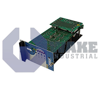
Wake Industrial LLC is not an authorized distributor of this product.
Wake Industrial LLC is not an authorized distributor of this product.
The Kollmorgen 67WKS-M240/3-PB is an analog servo amplifier in the 60wks Analog Servo Amplifiers series. It features a DC bus voltage of 240 VDC and has a peak output current of 10 A, with a rated output current of 3.5 A. The amplifier is protected by 3 x 16 A fuses and supports an output stage clock of 2 x 8.6 kHz.
Internal Product Review
The 67WKS-M240/3-PB is a Kollmorgen analog servo amplifier with a 240 VDC DC bus and 3.5 A rated output current. A 1 kHz current loop bandwidth and 10 A peak output current support crisp response and confident transient handling. This amplifier stands out as a well-tuned motion component for stable servo control.
 Have a part to sell?
 Wake Industrial Warranty
To contact sales for pricing and lead time:
Payment Methods


Shipping Methods


Our Credentials


Product Description:
The 67WKS-M240/3-PB is an analog servo amplifier produced by Kollmorgen within the 60wks Analog Servo Amplifiers series. It conditions current for permanent-magnet servomotors so that closed-loop position or velocity systems can follow reference commands in industrial automation machinery. Its analog control format also suits systems that rely on external motion electronics and continuously varying reference signals. By converting a regulated DC bus into a controlled, pulse-width-modulated output, the unit supplies the precise motor currents demanded by indexing tables, gantries, and packaging axes.
This amplifier draws a rated input of 0.6 kVA and operates from a DC link held at 240 VDC. Under steady load, it delivers a continuous phase current of 3.5 A, while momentary acceleration or load shock can be met with a peak of 10 A. The current regulator closes at 1 kHz, allowing tight torque control up to the mechanical bandwidth of most small servomotors. Input resistance of 150 kΩ ensures negligible load on upstream command sources, and a loop form factor of 1.01 keeps motor heating close to that of ideal sinusoidal excitation. A residual voltage drop of 5 V across the output stage must be considered when sizing motor back-EMF margins.
Protective and thermal operating details are also included. Overvoltage shutdown engages at 325 V, and the dual output stage clocks at 2 × 8.6 kHz to minimize audible noise while keeping switching losses predictable. At rated current, the converter dissipates 40 W, with an additional 15 W consumed during quiescent enabled status. Dynamic braking is handled by an internal ballast that absorbs 50 W continuously and up to 2.7 kW in pulses, preventing bus excursions during rapid deceleration. External safety fuses of 3 × 16 A, an auxiliary ±15 V sensor supply, and a DC bus residual current path complete the installation requirements.









