


21BRCX-510-D7B/10 Danaher
Wake Industrial LLC is not an authorized distributor of this product.
Wake Industrial LLC is not an authorized distributor of this product.
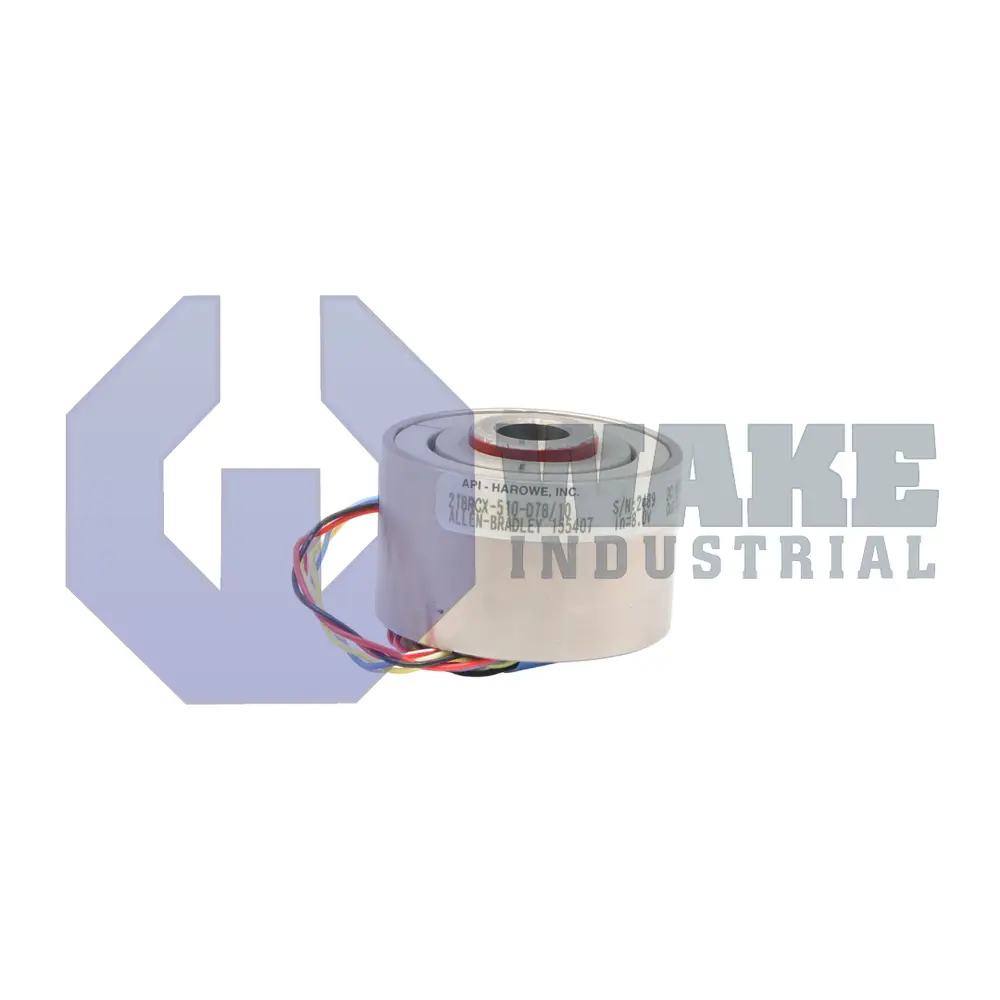
The Danaher 21BRCX-510-D7B/10 resolver is part of the Dynapar Resolvers series and features a steel housing measuring 1.25 inches in length with an outer diameter of 2.1 inches. It operates at a 4 kHz excitation frequency, has an input voltage of 8 Vrms with a 20 mA input current, and provides a transformation ratio of 0.25.
Internal Product Review
The 21BRCX-510-D7B/10 is a Danaher Dynapar resolver with an 8 Vrms input and 4 kHz excitation frequency. Steel housing and a low 15 mV null voltage support dependable signal stability in motion-feedback applications. A well-executed resolver choice for precise feedback where stable electrical performance is critical.
 Have a part to sell?
 Wake Industrial Warranty
To contact sales for pricing and lead time:
Payment Methods


Shipping Methods


Our Credentials


Product Description:
The 21BRCX-510-D7B/10 resolver is produced by Danaher within the Dynapar Resolvers series. As a rotary transformer, it couples an excitation signal into a rotor winding and returns two quadrature outputs that an industrial drive or motion controller converts into a real-time shaft angle. This sensor can be installed on servomotor housings or machine axes that require absolute position feedback that is resistant to electrical noise. Its transformer-based operation allows the receiving equipment to determine angular position without relying on optical components or direct electrical contact with the rotating element.
The control electronics send a carrier signal at 4 kHz and hold the primary at 8 Vrms; under these conditions, the resolver draws only 20 mA. At this drive level, the rotor presents an impedance of 210 + j410 Ω, while the stator presents an impedance of 110 + j180 Ω. These values establish the load placed on the excitation amplifier during operation. The sine and cosine secondary windings track the carrier with a fixed phase relationship and deliver outputs with a transformation ratio of 0.25. The rotor and stator resistances are 53 Ω and 40 Ω, respectively, which limits internal heating during continuous rotation. The device maintains a null voltage of 15 mV and a phase shift of +5.5° between the excitation and reference vectors. These electrical characteristics allow the receiving drive to establish an accurate electrical zero reference and process the resolver signals for closed-loop position control.
The resolver fits within a round steel housing that measures 2.1 in in diameter and 1.25 in in length, allowing installation in compact motor end bells. A pilot diameter of 2.061 in centers the body, and the shaft passes through a 0.5 in rotor bore. The mounting style omits a servo groove, so the unit seats flush against a mating surface and is secured with external hardware. Its laminated stack and winding geometry support straightforward offset compensation in digital feedback loops. The steel housing also provides magnetic shielding that helps protect the feedback signals from interference generated by nearby motor windings and power cables.