


VT-VSPA2-1-11A/T1 Bosch Rexroth Indramat
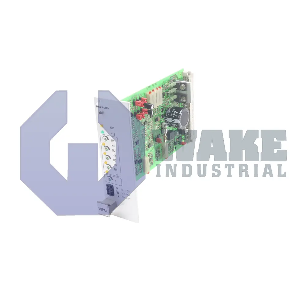
Wake Industrial LLC is not an authorized distributor of this product.
Wake Industrial LLC is not an authorized distributor of this product.
The Bosch Rexroth Indramat VT-VSPA2-1-11A/T1 is a proportional amplifier from the VT-VSPA Proportional Amplifiers series and operates with a supply voltage of 24 VDC. It features a maximum output current of 2.5 Amps and power consumption up to 50 VA. The device uses a 32-pin DIN 41612 Form D connector and has a current consumption limit of 2 Amps.
Internal Product Review
The VT-VSPA2-1-11A/T1 is a Bosch Rexroth Indramat proportional amplifier with a 24 VDC supply and 2.5 A max output current. A 32-pin DIN 41612 Form D connector and an 8.5 V minimum enable-on level support clean integration and dependable control response. The 50 VA max power consumption gives the unit an efficient and well-balanced profile for hydraulic control panels.
 Have a part to sell?
 Wake Industrial Warranty
To contact sales for pricing and lead time:
Payment Methods


Shipping Methods


Our Credentials


Product Description:
The VT-VSPA2-1-11A/T1 proportional amplifier is produced by Bosch Rexroth Indramat as part of the VT-VSPA Proportional Amplifiers series. Installed between a motion controller and a solenoid-actuated hydraulic valve, the board converts low-power command signals into controlled coil current that modulates spool position. By adjusting the pulse-width-modulated output, it supports closed-loop pressure or flow regulation in industrial automation systems that rely on electro-hydraulic actuation. This arrangement lets the controller shape hydraulic response without driving the valve coil directly.
Its nominal supply requirement is 24 VDC, and at this level the module draws up to 2 A for a maximum apparent power of 50 VA when all channels are energized. The output stage can deliver up to 2.5 A of coil current, while an internal bias current of 50 mA ± 25% helps prevent valve stick-slip near null. Pulse-width modulation runs at 300 Hz ± 10% for NG6 valves and at 180 Hz ± 10% for NG10 units, so the dither frequency matches different spool masses. An enable line must see at least 8.5 V before current flow begins, and the output is disabled when the signal falls below 6.5 V. A ready output provides at least 16 V at 50 mA to report healthy status to the PLC, and all terminations are routed through a 32-pin DIN 41612 Form D connector for quick rack mounting. Auxiliary ±9 V ± 1% rails are also available for external potentiometers.
Supply tolerance is broad because the amplifier remains functional down to 22 V and up to 35 V, which helps absorb battery sag or generator peaks often seen in mobile equipment. Circuit protection relies on a 3.15 AT fuse that disconnects the board before traces overheat, and a watchdog limits auxiliary demand to 25 mA so external sensor loads cannot overload the ±9 V reference. When the enable input is de-asserted, the 6.5 V off threshold guarantees zero coil excitation and allows the valve springs to return the spool to center.









