


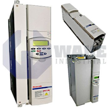
RD52.1-8N-015-L-V1-FW Bosch Rexroth Indramat
Wake Industrial LLC is not an authorized distributor of this product.
MPN: R911200982
No Tariffs On US Orders- Straightforward Pricing: No Rush Fees, No Credit Card Fees
The Bosch Rexroth Indramat RD52.1-8N-015-L-V1-FW is a drive controller from the RD 500 Drive Controllers series with a rated power of 15.0 kW and a voltage range of 700 V. It features field oriented vector control, forced air cooling, and lacks a built-in brake chopper. This drive controller supports 24 V external stand-by power and is designed for inverter DC supply.


To contact sales for pricing and lead time:
Payment Methods


Shipping Methods


Our Credentials


Product Description:
The RD52.1-8N-015-L-V1-FW drive controller is produced by Bosch Rexroth Indramat and belongs to the RD 500 Drive Controllers series. As a closed-loop power stage, it interfaces between an inverter DC link and the stator of an AC motor, supplying the regulated current and frequency needed for coordinated motion in automated machines and material-handling cells. It is optimized for cabinet installation where compact electronics simplify multi-axis layouts.
The controller operates with field-oriented vector control, so the internal processor resolves stator currents into torque-producing and magnetizing components, allowing precise torque linearity across the speed range. Thermal energy is carried away by forced air cooling, which moves ambient air across the heat sink to keep semiconductor junctions within acceptable limits during continuous duty. The power stage is rated for 15.0 kW, giving it capacity for mid-sized pumps, fans, or conveyor drives that are fed from a single cabinet slot. Its DC link is fed from an Inverter DC supply, which decouples the unit from line frequency and improves dynamic braking performance when a shared bus is present. The power electronics are designed for a nominal link voltage of 700 V, allowing the drive to serve high-voltage installations without additional step-up transformers.
The module is delivered without a built-in brake chopper, so regenerative energy must be dissipated through an external resistor or routed back to the common DC bus. Control electronics remain active during downtime because a service connector accepts 24 V standby power, letting diagnostics remain available while the main link is de-energized. The unit is generation 1, so it uses the connector pinouts and option cards assigned to that version in the RD 500 family. The required operating software is ordered as a separate subposition and is loaded to match the intended application.