


RD52.1-7N-045-L-V1-FW Bosch Rexroth Indramat 45 Kilowatt Forced Air Drive Controller
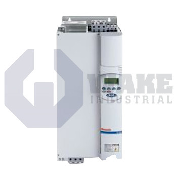
Wake Industrial LLC is not an authorized distributor of this product.
MPN: R911200463
No Tariffs On US Orders- Straightforward Pricing: No Rush Fees, No Credit Card Fees
The Bosch Rexroth Indramat RD52.1-7N-045-L-V1-FW is a drive controller from the RD 500 Drive Controllers series, offering a rated motor output of 45 kW at 400 V and 60 HP at 460 V. It features inverter DC supply with a voltage range of 530 to 670 V, forced air cooling, and supports field oriented vector control. The controller provides 2 digital inputs, 1 relay output, and analog input and output ranges from 0 to ±10 V or 0/4 to 20 mA.


To contact sales for pricing and lead time:
Payment Methods


Shipping Methods


Our Credentials


Product Description:
The RD52.1-7N-045-L-V1-FW is a drive controller from Bosch Rexroth Indramat’s RD 500 Drive Controllers series. Intended for inverter-supplied DC buses, the unit converts intermediate-circuit voltage into a three-phase output that drives induction or synchronous machines used in automated lines, packaging cells, and material-handling axes. By integrating control electronics with the power stage, it provides closed-loop speed and torque regulation while keeping cabinet wiring compact.
This controller operates on a DC link from 530 to 670 V, a range that allows direct connection to a 380 to 480 V front-end rectifier. Inside, a field-oriented vector control algorithm produces precise stator flux alignment, so rated torque is achieved at a continuous output of 82 A. Under 400 V motor conditions, the unit delivers 45 kW, and it can supply 60 HP when the motor base voltage is 460 V. Short bursts are accommodated by an overload current of 164 A for 0.5 s before the unit returns to its continuous rating. Heat from the power section is removed by forced air cooling, and the housing follows size class C for standard RD system mounting. I/O resources include one analog output range of 0 to 10 V or 0/4–20 mA, two digital inputs, and one changeover relay for contactor control.
Additional operating margins include overload limits of 139 A for 1 s and 107 A for 60 s. The unit has no built-in brake chopper, so external dynamic braking hardware is required when regenerative energy is expected. A standby circuit accepts DC 24 V with −15%/+20% tolerance and supports the 24 V external power function, so the control electronics can remain active during main bus shutdowns. The analog input interface covers 0 to ±10 V / 0/4–20 mA, matching common PLC transducers. The enclosure includes an internal forced-air path that helps keep semiconductor temperatures within limits during sustained operation.
Frequently Asked Questions about RD52.1-7N-045-L-V1-FW:
Q: What analog input ranges does the RD52.1-7N-045-L-V1-FW accept?
A: The RD52.1-7N-045-L-V1-FW supports analog inputs ranging from 0 to ±10 V or 0/4 to 20 mA.
Q: What is the rated motor output of the RD52.1-7N-045-L-V1-FW at 400 V?
A: This drive controller delivers a rated output of 45 kW when operating at 400 V.
Q: What cooling method is used in the RD52.1-7N-045-L-V1-FW drive controller?
A: Forced air cooling is used for the RD52.1-7N-045-L-V1-FW, ensuring efficient heat dissipation during operation.
Q: What is the rated current of the RD52.1-7N-045-L-V1-FW?
A: The rated current for the RD52.1-7N-045-L-V1-FW is 82 A.
Q: How many relay outputs are available on the RD52.1-7N-045-L-V1-FW?
A: This drive controller is equipped with one changeover contact relay output.









