


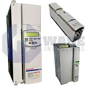
RD51.1-7N-005-P-V1-FW Bosch Rexroth Indramat
Wake Industrial LLC is not an authorized distributor of this product.
MPN: R911200702
No Tariffs On US Orders- Straightforward Pricing: No Rush Fees, No Credit Card Fees
The Bosch Rexroth Indramat RD51.1-7N-005-P-V1-FW is a drive controller from the RD 500 Drive Controllers series. It features U/f curve control and operates with a rated power of 5.5 kW. The unit is designed for inverter DC supply with a voltage range of 530 to 670 V and uses a heat dissipation panel for cooling.


To contact sales for pricing and lead time:
Payment Methods


Shipping Methods


Our Credentials


Product Description:
The RD51.1-7N-005-P-V1-FW is a drive controller manufactured by Bosch Rexroth Indramat for the RD 500 Drive Controllers series. It converts a fixed DC link into variable voltage and frequency so induction motors can be speed-regulated in automated conveyors, mixers, and material-handling stations. By integrating power semiconductors, gating logic, and fieldbus terminals in one chassis, the unit serves as a compact motion component that links a common DC bus to multiple motor axes while maintaining programmable acceleration and deceleration ramps. This arrangement also supports smooth starts and controlled speed changes across connected machine sections.
This controller accepts a stabilized link voltage of 530 to 670 V and is optimized for installations that feed it from a shared inverter DC bus. Its modulation follows U/f curve control, so the microprocessor scales stator voltage with frequency to keep magnetic flux relatively constant during operation. A nominal output of 5.5 kW is available for continuous motor duty without derating. Thermal energy is removed through a heat dissipation panel (≤ 18.5 kW), which transfers losses to the cabinet wall and permits natural convection inside the enclosure. This control method is well suited to steady-speed applications such as pumps and fans, where simple open-loop operation is often sufficient.
The RD51.1 platform is supplied without a built-in brake chopper, so surplus regenerative energy must be routed to an external braking resistor when rapid stops are required. Control electronics remain active during main disconnects when the standby terminal is wired for 24 V standby power from an external source, allowing diagnostics and parameter access without energizing the DC link. The hardware is classified as Design Generation 1, which places the unit in the first release of this design platform. For software configuration, firmware is ordered as a separate subposition. This approach allows the drive to be matched to the required operating language and application feature set while keeping the power section unchanged.
Frequently Asked Questions about RD51.1-7N-005-P-V1-FW:
Q: What is the rated power capacity of the RD51.1-7N-005-P-V1-FW drive controller?
A: The RD51.1-7N-005-P-V1-FW has a rated power output of 5.5 kW.
Q: Which control method is utilized by the RD51.1-7N-005-P-V1-FW?
A: This controller uses U/f curve control as its primary control method.
Q: What cooling method is implemented in the RD51.1-7N-005-P-V1-FW drive controller?
A: The RD51.1-7N-005-P-V1-FW is designed to dissipate heat using a panel for applications up to 18.5 kW.
Q: What is the voltage input range for the RD51.1-7N-005-P-V1-FW?
A: Its supply voltage range is from 530 to 670 V.
Q: Does the RD51.1-7N-005-P-V1-FW include a brake chopper?
A: This drive controller operates without a built-in brake chopper.









