


RD51.1-7N-003-L-V1-FW Bosch Rexroth Indramat
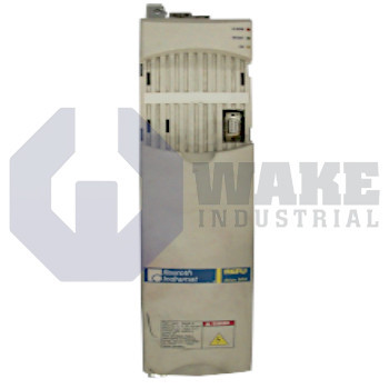
Wake Industrial LLC is not an authorized distributor of this product.
MPN: R911200313
No Tariffs On US Orders- Straightforward Pricing: No Rush Fees, No Credit Card Fees
The Bosch Rexroth Indramat RD51.1-7N-003-L-V1-FW is a drive controller from the RD 500 Drive Controllers series. It features U/f curve control, operates with a rated power of 3.0 kW, and utilizes forced air cooling. The unit supports an external 24 V stand-by power function and is designed for inverter DC supply with a voltage range of 530 to 670 V.


To contact sales for pricing and lead time:
Payment Methods


Shipping Methods


Our Credentials


Product Description:
The RD51.1-7N-003-L-V1-FW is a drive controller produced by Bosch Rexroth Indramat for the RD 500 Drive Controllers series. Within an automation cell, it converts energy from a regulated DC bus into a variable-frequency, variable-voltage output so an induction motor can accelerate, decelerate, or hold a set speed according to the machine program. It is suited to industrial applications such as conveyors, fans, and general process machinery where adjustable motor speed improves control of the driven load. This operating method also supports straightforward integration in systems that already use a shared DC supply.
This model delivers a nominal output of 3.0 kW, making it suitable for motors in the 4 hp class that run continuous duty cycles. It accepts a DC link between 530 to 670 V, so it can connect to common rectifier sections in multi-axis systems. Speed is controlled with U/f curve control, which maintains a fixed voltage-to-frequency ratio so the motor operates with steady magnetic flux without closed-loop feedback hardware. Internal components are cooled by forced air cooling, which moves cabinet air across the power semiconductors to keep junction temperatures within limits when the unit runs at full rated current. The power stage is classified as Inverter DC, so it is supplied solely from a DC bus and does not contain its own mains rectifier.
Because it is delivered without a built-in brake chopper, dynamic braking energy must be handled by an external resistor or a separate chopper module. An auxiliary line provides 24 V standby power, so the control electronics can remain active during mains isolation for parameter retention and communication functions. Keeping the electronics energized during shutdown can preserve operating data while the power stage is inactive. The product is Design Generation 1, which matches the mounting dimensions and option-card format used in the first RD 500 generation.
Frequently Asked Questions about RD51.1-7N-003-L-V1-FW:
Q: Does the RD51.1-7N-003-L-V1-FW drive controller have a built-in brake chopper?
A: The RD51.1-7N-003-L-V1-FW does not include a built-in brake chopper.
Q: What control type is employed by the RD51.1-7N-003-L-V1-FW drive controller?
A: This controller uses U/f curve control for managing motor operation.
Q: How is the RD51.1-7N-003-L-V1-FW drive controller cooled?
A: Forced air cooling is used in the RD51.1-7N-003-L-V1-FW to dissipate heat during operation.
Q: What is the rated power of the RD51.1-7N-003-L-V1-FW drive controller?
A: The RD51.1-7N-003-L-V1-FW features a rated power output of 3.0 kW.
Q: What voltage range can the RD51.1-7N-003-L-V1-FW accept for operation?
A: It operates within a voltage range of 530 to 670 V from an inverter DC supply.









