


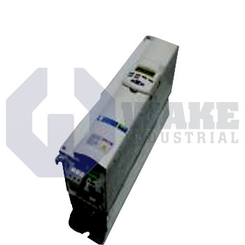
RD51.1-5B-015-L-CF-FW Bosch Rexroth Indramat
Wake Industrial LLC is not an authorized distributor of this product.
Wake Industrial LLC is not an authorized distributor of this product.
MPN: R911203231
Ask for AvailabilityThe Bosch Rexroth Indramat RD51.1-5B-015-L-CF-FW is a drive controller from the RD 500 Drive Controllers series. It features a rated power of 15.0 kW and operates on a 500 V, 3-phase AC supply. This unit has U/f curve control, forced air cooling, and comes equipped with a built-in brake chopper.
Internal Product Review
The RD51.1-5B-015-L-CF-FW is a Bosch Rexroth Indramat drive controller with U/f curve control and a built-in brake chopper. Forced air cooling supports stable operation, and the 15.0 kW rating makes the controller a strong fit for demanding drive applications.
 Have a part to sell?
 Wake Industrial Warranty
To contact sales for pricing and lead time:
Payment Methods


Shipping Methods


Our Credentials


Product Description:
The RD51.1-5B-015-L-CF-FW is a modular drive controller produced by Bosch Rexroth Indramat in the RD 500 Drive Controllers series. It is intended for panel-mounted integration in automation lines where variable-speed three-phase induction motors require coordinated torque and speed regulation. By converting fixed-frequency mains power into a regulated AC output, the unit serves as the interface between a programmable logic controller and the motor. This arrangement allows conveyors, pumps, and material-handling axes to follow commanded speed profiles without relying on mechanical contactors for routine motor control. Because the controller modulates output frequency and voltage electronically, motor acceleration and steady-state operation can be adjusted without switching the motor directly across the line.
This model is designed for systems that draw up to 15.0 kW of mechanical shaft power during continuous duty. The power section can accept a DC link based on 500 V through a front-end rectifier, giving the inverter stage the bus voltage needed to synthesize motor output. It is classified as a Converter 3 x AC, which means the output stage supplies three-phase voltage to the motor terminals. Speed reference is handled with U/f curve control, an open-loop method that keeps stator voltage and frequency in proportion so magnetic flux remains stable in standard-efficiency induction motors. That control approach suits applications where precise encoder-based positioning is not required but stable speed behavior under varying load remains important.
Thermal limits are managed by forced air cooling, so cabinet airflow must stay available to remove heat from the IGBT section and associated braking circuitry. For dynamic stops and overhauling loads, a built-in brake chopper routes excess DC-bus energy to an external resistor and helps prevent overvoltage trips during deceleration. The application layer can be expanded through Combination: C1 + F1, which provides standard speed-regulation functions together with selectable fieldbus communication. When braking energy is dissipated externally, the DC bus can remain within its operating window during frequent deceleration events. This setup supports use in installations that need basic motor control as well as networked integration with higher-level automation equipment.