


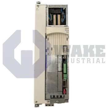
RD51.1-5B-011-L-D1-FW Bosch Rexroth Indramat
Wake Industrial LLC is not an authorized distributor of this product.
Wake Industrial LLC is not an authorized distributor of this product.
MPN: R911200396
Ask for AvailabilityThe Bosch Rexroth Indramat RD51.1-5B-011-L-D1-FW is a drive controller from the RD 500 Drive Controllers series and is designed for converter 3 x AC supply with a voltage range of 500 V. This model features forced air cooling, a built-in brake chopper, and U/f curve control. It is equipped with a NAMUR terminal strip and supports 24 V external stand-by power.
Internal Product Review
The RD51.1-5B-011-L-D1-FW is a Bosch Rexroth Indramat drive controller designed for converter 3 x AC systems at 500 V. Forced air cooling and a built-in brake chopper support stable thermal management and dependable deceleration performance. U/f curve control makes this unit a strong choice for consistent drive regulation.
 Have a part to sell?
 Wake Industrial Warranty
To contact sales for pricing and lead time:
Payment Methods


Shipping Methods


Our Credentials


Product Description:
The RD51.1-5B-011-L-D1-FW is a drive controller manufactured by Bosch Rexroth Indramat for the RD 500 Drive Controllers series. It converts fixed three-phase mains into a variable-frequency output for asynchronous motors, allowing PLC-controlled systems to regulate speed with stable torque response. This role makes it suitable for material-handling lines, centrifuges, and packaging stations where compact panel installation and dependable motor control are required. It can serve applications that need gradual acceleration, repeatable deceleration, and steady operation across changing load conditions.
Motor excitation is governed by U/f curve control, which keeps the voltage-to-frequency ratio proportional so motor flux remains steady across the speed range. The input stage uses a three-phase AC converter and operates on a DC bus rated for 500 V. Heat from the power section is removed by forced-air cooling, so the cabinet must provide a clear airflow path. A built-in brake chopper diverts regenerated energy to an external resistor during deceleration and helps limit bus overvoltage. Field wiring is arranged through a NAMUR terminal strip with external 24 V standby power, which allows the control section to remain active when the main power is switched off. That arrangement also keeps diagnostic functions available during control-level power transitions.
The unit is built to Design Generation 1, so wiring positions, fan orientation, and control board layout follow the early format used in this generation. The drive uses separate firmware ordering, which lets the software package be selected for the intended application. Its parameter memory retains ramp settings, drive tuning values, and fault history through a main power loss. Stored data remains available after the incoming supply is removed, which helps the controller resume the same operating behavior when power returns.