


RD51.1-4B-004-L-V1-FW Bosch Rexroth Indramat
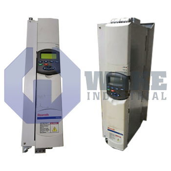
Wake Industrial LLC is not an authorized distributor of this product.
MPN: R911200141
No Tariffs On US Orders- Straightforward Pricing: No Rush Fees, No Credit Card Fees
The Bosch Rexroth Indramat RD51.1-4B-004-L-V1-FW is a drive controller from the RD 500 Drive Controllers series. It features U/f curve control, an integrated mains filter, and a built-in brake chopper. The controller uses forced air cooling and operates with a voltage range of 380 to 480 V with a ±10% tolerance.


To contact sales for pricing and lead time:
Payment Methods


Shipping Methods


Our Credentials


Product Description:
The RD51.1-4B-004-L-V1-FW is a drive controller from Bosch Rexroth Indramat in the RD 500 Drive Controllers series. It serves as the central power stage between a three-phase mains supply and an asynchronous motor, supplying adjustable voltage and frequency for variable-speed operation in conveyors, production lines, and similar automated equipment. By regulating motor flux, the unit supports smooth acceleration, stable throughput, and controlled speed changes during routine process demands. This operating approach helps reduce abrupt mechanical loading on connected drivetrain components during starts and stops.
The controller accepts an input range of 380 to 480 V, with an allowable variation of ±10 % for operation on industrial power systems with moderate fluctuation. It uses U/f curve control to maintain a consistent magnetizing relationship across the speed range, which supports steady motor behavior in general-purpose drive applications. A built-in brake chopper absorbs regenerated energy during deceleration so the DC link is less likely to rise to an excessive voltage. This function is useful when the driven load returns energy during fast stopping or overhauling conditions. Heat is removed by forced air cooling, so the enclosure must provide clear airflow paths to maintain continuous operating capability.
An integrated mains filter helps reduce conducted emissions and can lessen the need for additional external filtering components in the supply path. The control electronics can remain active from 24 V standby power, which allows communication and parameter access when the main power stage is switched off. The unit is Version 1 and uses a 3 x AC converter supply arrangement, so input wiring must follow the required three-phase and protective earth connections. With the control section still energized, stored settings can be reviewed or adjusted without energizing the motor output stage.