Product Description
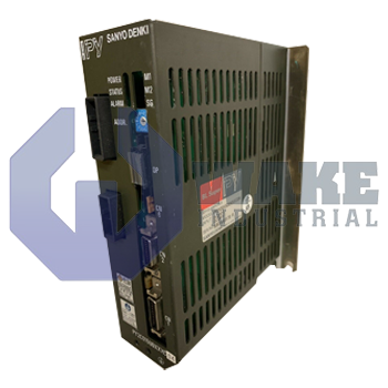
The PY2C015U0XXXC04 servo amplifier from Sanyo Denki is used with servomotors from the manufacturer. The PY series amplifier features 15A current rating, 5V control power supply and 280VDC voltage rating. Parameters can be assigned or modified using a remote operator or by installing the traditional PC-Setup PY software. The PY software has an added advantage of allowing you to make a backup copy of the configuration. This can be useful if the same configuration is needed at a later time. After unpacking the amplifier from its box, check to see that the model number on the product matches the number given on the box.
When the amplifier is installed near a vibration source, a shock absorber must also be installed along with it. This helps in dampening any vibration that will otherwise get directly transmitted to the unit. The amplifier must not be kept in a horizontal position during the installation process. There must be a space of at least 10mm on all four sides of the device to allow for air circulation on the sides and prevent it from getting heated up. The unit features an ideal operating temperature range of 0°C to 55°C. The remote operator of the amplifier supports five operation modes. These are Parameter Select, Parameter Set, Alarm Trace, Monitor, and Test.
During the installation process, the ground signals of the amplifier must be connected first. The bus circuit wiring must be kept away from the signal wiring to avoid interference. The amplifier does not incorporate shorting bars. The LED display features two modes History and Gain. The desired mode can be selected using a DIP switch that is present on top of the display. The bus power connection can be removed from the amplifier during normal operation while leaving the control power connection intact. This helps to create a safe operating environment.

 Wake Industrial Warranty